Do you have a question about the Danelec DM100-2014 and is the answer not in the manual?
List of related documents for further information.
Definitions and acronyms used throughout the manual.
Description of the DAU, the main data collection unit.
Description of the Bridge Control Panel interface.
Description of the Bridge Microphone Units.
Description of the fixed data capsule's installation and purpose.
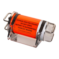
Description of the float-free capsule, a required component.
Description of the optional RVI for video capture.
Description of the optional SIU for additional interfaces.
Details on interface capacity for different configurations.
Overview of the BCP user interface and its functions.
How system errors are indicated on the BCP.
Procedure for performing the VDR self-test.
How to reset the BCP display brightness.
Details on the DPU, the system's main computer.
Explanation of the DPU's power status LEDs.
Description of the DPU's AC power breaker.
Information on the DPU's AC power connection.
Function of the DPU's battery switch.
Interpretation of the VDR system status LED.
Meaning of the DPU's Main CPU status LED.
Description of LEDs on Ethernet ports.
Description of LEDs on the Uni-rack.
Details on Ethernet port indicators.
Configuration of the UR address.
Description of LEDs on the Module Rack.
Details on Ethernet connector LEDs.
Mapping of digital interface labels.
Configuration of the MR address.
Using the RVI with AC power.
Configuration of the RVI address.
Description of RVI Ethernet ports.
Explanation of the RVI Status LED.
Comprehensive list of system error codes and their meanings.
Procedure for verifying VDR function after service.
Catalogue of frequently used spare parts.
| Brand | Danelec |
|---|---|
| Model | DM100-2014 |
| Category | Data Loggers |
| Language | English |