Operator's Manual for the DM100-2014 VDR
Copyright Danelec Marine A/S
4.1.4 Battery switch
The battery switch indirectly controls a relay between the DPU and the battery pack. When
switching the VDR off; do the following: Pop out the AC breaker and briefly move the battery
switch to its “OFF” position. Move the battery switch back to its “ON” after the VDR is turned off.
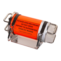
4.1.5 VDR status LED
The status of the system is displayed using a tri-color LED. The BCP will display text messages and
error codes explaining the problem(s) if the LED becomes yellow or red.
VDR status LED (tri color)
The information displayed is just
information
The information displayed is a warning.
The system is still fully operational but
may fail soon. Contact a service agent if
the problem cannot be rectified.
The information displayed contains
information about system errors which
prevent normal operation. Contact a
service agent if the problem cannot be
4.1.6 Main CPU LED
The main CPU LED is controlled by the power control circuit which will become active as the first
circuit after power is applied. The power circuit uses the LED to show information about the main
CPU.
The power circuit has not started yet –
this should take a few seconds only.
The power circuit is waiting for the main
CPU to start (boot load) – may take up to
The main CPU is operating normally
The main CPU is not responding
4.1.7 LEDs in the Ethernet connectors
Two LEDs are integrated into each Ethernet connector. The left LED will be illuminated when a
communication link is established and shows the speed (yellow = 100Mbit/sec, green =
1000Mbits/sec). The right LED (green) will be illuminated when a communication link is
established and will flicker depending on the traffic load.
DBS11011-12 Page 12/27