Operator's Manual for the DM100-2014 VDR
Copyright Danelec Marine A/S
Contents
REVISION RECORD ........................................................................................................... 2
1 SCOPE AND PURPOSE .......................................................................................... 5
1.1 References ................................................................................................................ 5
1.2 Terms and Abbreviations .......................................................................................... 5
2 SYSTEM OVERVIEW ............................................................................................... 6
2.1.1 Data Acquisition Unit (DAU) ............................................................................... 6
2.1.2 VDR Bridge Control Panel (BCP) ....................................................................... 6
2.1.3 Bridge Microphone Units (BMU) ........................................................................ 6
2.1.4 Fixed capsule ..................................................................................................... 7
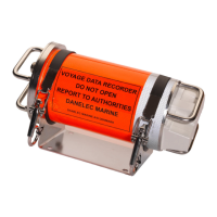
2.1.5 Float-free capsule .............................................................................................. 7
2.1.6 Remote Video Interface (RVI) ............................................................................ 7
2.1.7 Sensor Interface Unit (SIU) ................................................................................ 7
2.2 Maximum number of supported interfaces ................................................................ 8
3 OPERATION ............................................................................................................. 9
3.1 Bridge Control Panel ................................................................................................. 9
3.1.1 Alarm display ..................................................................................................... 9
3.1.2 Self-test – Operational Performance Test .......................................................... 9
3.1.3 Setting the display brilliance level to default ...................................................... 9
4 OPERATION OF THE DM100 DAU ....................................................................... 10
4.1 Data Processing Unit (DPU).................................................................................... 11
4.1.1 Power LEDs ..................................................................................................... 11
4.1.2 AC breaker ....................................................................................................... 11
4.1.3 AC inlet ............................................................................................................ 11
4.1.4 Battery switch ................................................................................................... 12
4.1.5 VDR status LED ............................................................................................... 12
4.1.6 Main CPU LED ................................................................................................. 12
4.1.7 LEDs in the Ethernet connectors ..................................................................... 12
5 OPERATION OF THE NON-MODULAR COMPACT SIU ...................................... 13
5.1 LEDs on the Uni-rack .............................................................................................. 13
5.1.1 AC LED ............................................................................................................ 13
5.1.2 AC breaker ....................................................................................................... 13
5.1.3 Ethernet link and activity indicators .................................................................. 14
5.1.4 UR address ...................................................................................................... 14
6 OPERATION OF THE MODULAR SIU .................................................................. 15
6.1 LEDs on Module Rack ............................................................................................ 15
6.1.1 AC LED ............................................................................................................ 15
6.1.2 Link indications ................................................................................................ 15
DBS11011-12 Page 3/27