Operator's Manual for the DM100-2014 VDR
Copyright Danelec Marine A/S
9 Service and maintenance
The VDR requires an annual performance test carried out by a certified service organization. Please
refer to “Installation Manual for DM100-2014 VDR” for further details.
9.1 Verification of the VDR functionality following service on any
sensor
It is a requirement of the VDR standard that the functionality of the VDR is verified following
service on any sensor (e.g. the GPS) connected to the VDR. A self-test (Operational Performance
Test) may be started from the BCP, see section 3.1.2.
9.2 List of most common spare parts
Uni Rack UR 06-002 - 8ch analog
RVI with PoE (for DM100) 2 x 5 x BNC
RVI with PoE (for DM100) 2 x DVI-I
MK4 capsule with cradle, beacon and 50m cable
VDR Bridge Control Panel BCP
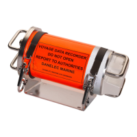
MK1 float-free capsule with 50m cable and junction box
BMU 003 - Bridge Microphone Unit Indoor, BMU-I 2014
BMU 004 - Bridge Microphone Unit Outdoor, BMU-O 2014
Ethernet Interface for Capsule MK4 - assembled PCB
Set of fans (2) for DPU 100-01 (spare part)
Battery pack and fans(2) for DPU 100-01 (spare part)
50m zero halogen FTP CAT5 cable w. RJ45 and Wago for capsule MK4 and FF MK1
Boot flash for DM100-2014 VDR
Manual for compact Sensor Interface Unit (hard copy and CD)
Set of manuals for the DM100-2014 VDR (Hardcopy and CD)
DBS11011-12 Page 27/27