40 Capacity controller RS8GN202 © Danfoss 11-2013 AK-PC 783
11
Signal Module Point Terminal Active at
Compressor 1 Gen. Safety MT
4
1 (DI 1) 1 - 2 Open
Compressor 2 Gen. Safety MT 2 (DI 2) 3 - 4 Open
Compressor 3 Gen. Safety MT 3 (DI 3) 5 - 6 Open
Compressor 4 Gen. Safety MT 4 (DI 4) 7 - 8 Open
All compressors common safety MT 5 (DI 5) 9 - 10 Open
All compressors common safety LT 6 (DI 6) 11 - 12 Open
Compressor 1 Gen. Safety LT 7 (DI 7) 13 - 14 Open
Compressor 2 Gen. Safety LT 8 (DI 8) 15 - 16 Open
Signal Module Point Terminal Signal type
Temp. heat exchanger Scasc2
5
1 (AI 1) 1 - 2 Pt 1000
Temp. heat exchanger Scasc3 2 (AI 2) 3 - 4 Pt 1000
3 (AI 3) 5 - 6
Oil receiver, Prec Oil
4 (AI 4) 7 - 8
AKS 2050-59
Speed control, compressor MT 5 (AO 1) 9 - 10
0 - 10 V
Speed control, compressor LT 6 (AO 2) 11 - 12 0 - 10 V
Speed control, EC motor 7 (AO 3) 13 - 14 0 - 10 V
8 (AO 4) 15 - 16
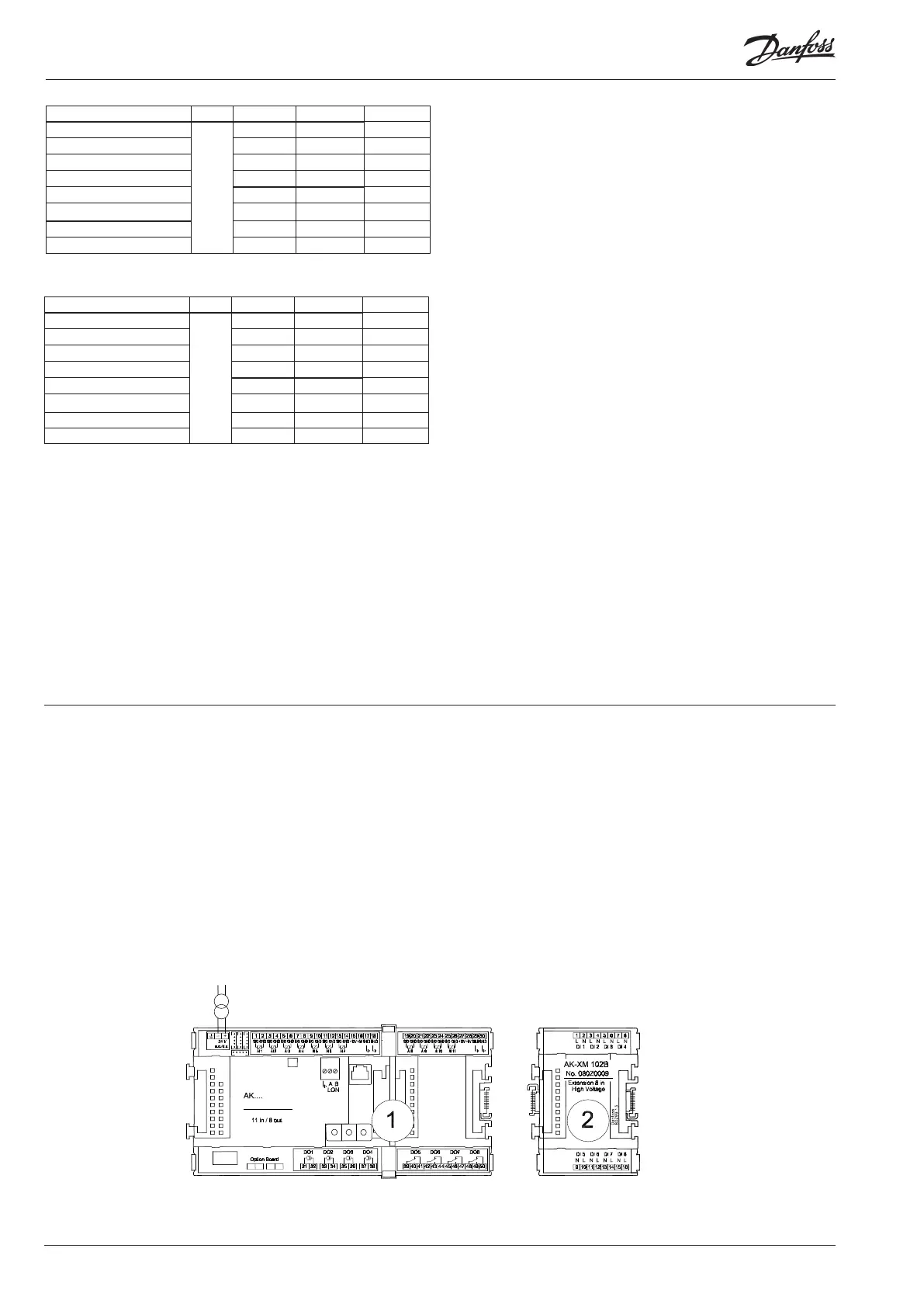
Connection diagram
Drawings of the individual modules may be
ordered from Danfoss.
Format = dwg and dxf.
You may then yourself write the module
number in the circle and draw the individual
connections.
The supply voltage for the pressure
transmitter should be taken from
the same module that receives the
pressure signal.
GND connection to a sensor signal
must be made on the same module
receiving the temperature signal.