48 Capacity controller RS8GN202 © Danfoss 11-2013 AK-PC 783
Wiring
Decide during planning which function is to be connected and
where this will be.
1. Connect inputs and outputs
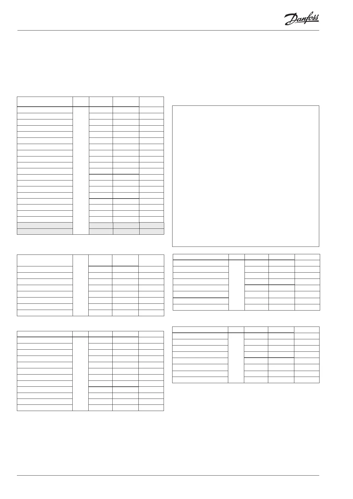
Here are the tables for the example:
Mounting and wiring - continued
The function of the switch functions can be seen in the last column.
There are pressure transmitters AKS 32R and AKS 2050 available for
several pressure ranges.
Here there are three dierent ones. One up to 12 bar, 34 bar and 59 bar.
Signal Module Point
Terminal
Signal type /
Active at
Discharge gas temperature - Sd-MT
1
1 (AI 1) 1 - 2 Pt 1000
Suction gas temperature - Ss-MT 2 (AI 2) 3 - 4 Pt 1000
Outdoor temperature - Sc3 3 (AI 3) 5 - 6 Pt 1000
Discharge gas temperature - Sd-LT 4 (AI 4) 7 - 8 Pt 1000
Suction gas temperature - Ss-LT 5 (AI 5) 9 - 10 Pt 1000
Suction pressure - P0-MT 6 (AI 6) 11 - 12 AKS 32R-12
Condenser pressure - Pc-MT 7 (AI 7) 13 - 14 AKS 32R-34
Level switch, oil, comp. 1 LT 8 (AI 8) 19 - 20 closed
Level switch, oil, comp..2 LT 9 (AI 9) 21 - 22 closed
10 (AI 10) 23 - 24
11 (AI 11) 25 - 26
Solenoid valve, oil, Comp. 1 LT 12 (DO 1) 31 - 32 ON
Solenoid valve, oil, Comp. 2 LT 13 (DO 2) 33 - 34 ON
14 (DO 3) 35 - 36
15 (DO 4) 37 - 38
Solenoid valve , oil, Separator 16 (DO 5) 39 - 40 - 41 ON
Solenoid valve, cascade 17 (DO6) 42 - 43 - 44 ON
EC motor on/o signal 18 (DO7) 45 - 46 - 47 ON
19 (DO8) 48 - 49 - 50
24 -
25 -
Remember the isolation amplier
If signals are received from dierent controls, e.g. heat re-
covery for one of the inputs, a galvanically insulated module
should be inserted.
Signal Module Point
Terminal
Signal type /
Active at
Compressor 1 MT
2
1 (DO 1) 25 - 26 - 27 ON
Compressor 2 MT 2 (DO 2) 28 - 29 - 30 ON
Compressor 3 MT 3 (DO 3) 31 - 32 - 33 ON
Compressor 4 MT 4 (DO 4) 34 - 35 - 36 ON
Compressor 1 LT 5 (DO 5) 37 - 38 - 39 ON
Compressor 2 LT 6 (DO6) 40 - 41 - 42 ON
7 (DO7) 43 - 44 - 45
8 (DO8) 46 - 47 - 48
Signal Module Point/Step Terminal Signal type
Level switch, oil, receiver High
3
1 (AI 1) 1 - 2 Closed
Level switch, oil, receiver Low 2 (AI 2) 3 - 4 Closed
Level switch, oil, Separator, High 3 (AI 3) 5 - 6 Closed
4 (AI 4) 7 - 8
5 (AI 5) 9 - 10
Pulse reset of stopped compressor 6 (AI 6) 11 - 12 Pulse
Suctioon pressure - P0-LT 7 (AI 7) 13 - 14 AKS 2050-59
Condenser pressure - Pc-LT 8 (AI 8) 15 - 16 AKS 2050-59
Stepper signal til ETS valve 1 (AO 1)
25 - 26 - 27 - 28
ETS
2 (AO 2) 29 - 30 - 31 - 32
3 (AO 3) 33 - 34 - 35 - 36
4 (AO 4) 37 - 38 - 39 - 40
Signal Module Point Terminal Active at
Compressor 1 Gen. Safety MT
4
1 (DI 1) 1 - 2 Open
Compressor 2 Gen. Safety MT 2 (DI 2) 3 - 4 Open
Compressor 3 Gen. Safety MT 3 (DI 3) 5 - 6 Open
Compressor 4 Gen. Safety MT 4 (DI 4) 7 - 8 Open
All compressors common safety MT 5 (DI 5) 9 - 10 Open
All compressors common safety LT 6 (DI 6) 11 - 12 Open
Compressor 1 Gen. Safety LT 7 (DI 7) 13 - 14
Open
Compressor 2 Gen. Safety LT 8 (DI 8) 15 - 16
Open
Signal Module Point Terminal Signal type
Temp. heat exchanger Scasc2
5
1 (AI 1) 1 - 2 Pt 1000
Temp. heat exchanger Scasc3 2 (AI 2) 3 - 4 Pt 1000
3 (AI 3) 5 - 6
Oil receiver, Prec Oil 4 (AI 4) 7 - 8 AKS 2050-59
Speed control, compressor MT 5 (AO 1) 9 - 10 0 - 10 V
Speed control, compressor LT 6 (AO 2) 11 - 12 0 - 10 V
Speed control, EC motor 7 (AO 3) 13 - 14 0 - 10 V
8 (AO 4) 15 - 16