AK-PC 783 Capacity controller RS8GN202 © Danfoss 11-2013 75
Conguration of inputs
and outputs
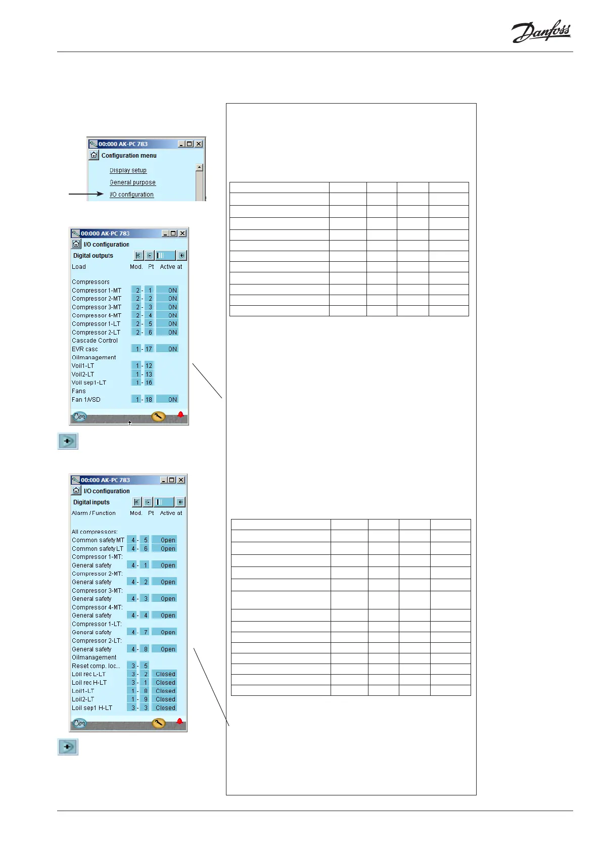
1. Go to Conguration menu
2. Select I/O conguration
3. Conguration of Digital outputs
Press the +-button to go on to the
next page
4. Setup On/o inputs
Press the +-button to go on to
the next page.
Conguration - continued
3 - Outputs
The possible functions are
the following:
Comp. 1
Unloader 1-1
Unloader 1-2
Unloader 1-3
Do for Compressor. 2-4
Oil valve comp. 1-4
Lp comp. oil pulse
Oil valve 1-4
Oil valve separat. 1-4
MT Comp. release
LT Comp. request
Injection heat exchanger
Injection suction line
Injection ON
Fan 1 / VSD
Fan 2 - 8
Heat recovery
Valve tap water V3tw
Pump tap water tw
Valve heat recov. V3hr
Pump heat recov. hr
Alarm
I'm alive relay
Thermostat 1 - 3
Pressostat 1 - 3
Volt input 1 - 3
PI 1-3
4 - Digital inputs
The possible functions are
the following:
Ext. Main switch
Ext. compr. stop
Ext. power loss
Night setback
Load shed 1
Load shed 2
All compressors:
Common safety
Comp. 1
Oil pressure safety
Over current safety
Motor protect. safety
Disch. temp. safety
Disch. press. safety
General safety
VSD comp. 1 Fault
Do for Comp. 2-4
Fan 1 safety
Do for fan 2-4
VSD cond safety
Reset comp. lockout
LP comp.oil counter
Oil receiver low
Oil receiver high
Oil level comp.1-4
Oil separator low 1-4
Oil separator high 1-4
Heat recovery
tw enable
hr enable
Flow switch tw
Flow switch hr
DI 1 Alarm input
DI 2-10 ...
PI-1 Di ref
External DI PI-1
The following displays will depend on the earlier denitions. The dis-
plays will show which connections the earlier settings will require. The
tables are the same as shown earlier.
• Digital outputs
• Digital inputs
• Analog outputs
• Analog inputs
We set up the controller’s digital input functions by keying in which
module and point on this module each one of these has been connected
to.
We furthermore select for each output whether the function is to be ac-
tive when the output is in pos. Closed or Open.
Open has been selected here for all the safety circuits. This means that
the controller will receive signal under normal operation and register it
as a fault if the signal is interrupted.
We set up the controller’s digital outputs by keying in which module
and point on this module each one of these has been connected to.
We furthermore select for each output whether the load is to be active
when the output is in pos. ON or OFF.
Load Output Module Point Active at
Solenoid valve, oil, Comp. 1 LT DO1 1 12 ON
Solenoid valve, oil, Comp. 2 LT DO2 1 13 ON
Solenoid valve, oil separator DO5 1 16 ON
Solenoid valve, cascade D06 1 17 ON
EC motor ON/OFF signal DO7 1 18 ON
Compressor 1, MT DO1 2 1 ON
Compressor 2, MT DO2 2 2 ON
Compressor 3. MT DO3 2 3 ON
Compressor 4, MT DO4 2 4 ON
Compressor 1, LT DO5 2 5 ON
Compressor 2, LT DO6 2 6 ON
Function Input Module Point Active at
Level switch, oil, comp.1 LT AI8 1 8 Closed
Level switch, oil, comp.2 LT AI9 1 9 Closed
Level switch, oil, receiver High AI1 3 1 Closed
Level switch, oil, receiver Low AI2 3 2 Closed
Level switch, oil, Separator High AI3 3 3 Closed
Reset of compressor stop AI5 3 5
Pulse pres-
sure
Compressor 1 Gen. Safety MT DI1 4 1 Open
Compressor 2 Gen. Safety MT DI2 4 2 Open
Compressor 3 Gen. Safety MT DI3 4 3 Open
Compressor 4 Gen. Safety MT DI4 4 4 Open
All compressors common safety MT DI5 4 5 Open
All compressors common safety LT DI6 4 6 Open
Compressor 1 Gen. Safety LT DI7 4 7 Open
Compressor 2 Gen. Safety LT DI8 4 8 Open