74 Capacity controller RS8GN202 © Danfoss 11-2013 AK-PC 783
Conguration - continued
1. Select PI functions
2. Select actual PI-function
3. Dene the required names
and values attached to the
function
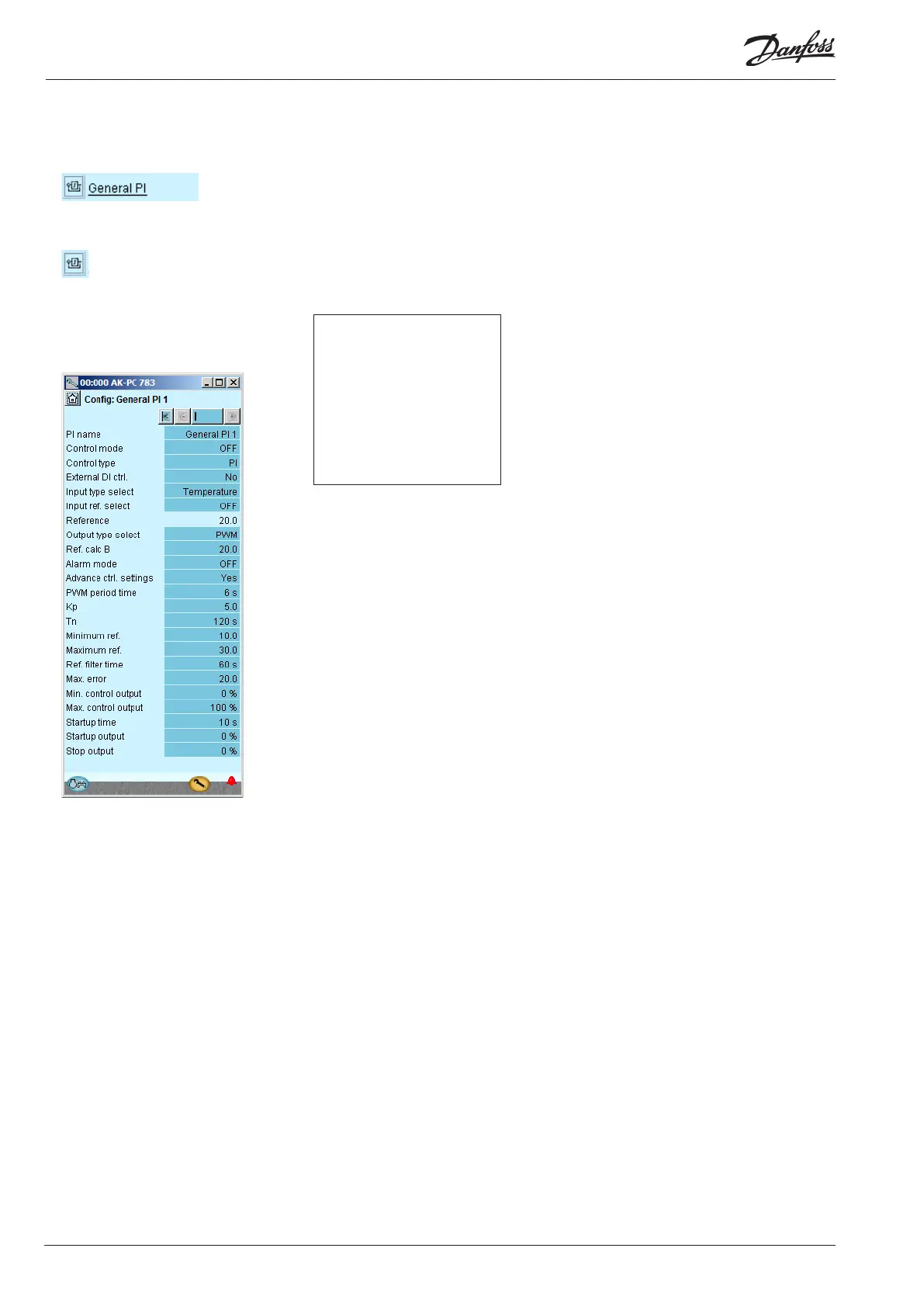
Separate PI functions
In our example we do not use
this function, so the display
has been included for your
information only.
3 - General PI Control
The function can be used for optional regulation.
Adjust for each regulation
• Name
• Control mode: O, Manual or Auto
• Control type: P or PI
• External DI ctrl: Adjusted to On if there is an external switch
that can start/stop the regulation.
• Input type: Choose which signal the regulation shall receive:
Temperature, pressure, pressure converted to temperature,
, voltage signal, Tc, Pc, Ss or Sd.
• Signal at variable reference: Choose between: : Non,
temperature, pressure, pressure converted to temperature,
voltage signal, Tc, Pc, Ss or DI.
• Reading the signal for the variable reference (not shown in
the display)
• Reading the total reference
• Output. Here you select the outlet function (PWM = pulse
width modulated (fx AKV valve)), Stepper signal for a step-
per motor or voltage signal.
• Ref. calc A: Constant for variable value included in the refer-
ence. (Reference = Ax + B)
• Ref. calc B: Fixed value included in reference
• Alarm mode: Choose whether an alarm shall be attached to
the function. If it is set to ON, alarm texts and alarm limits
can be entered.
• Advanced ctrl. settings: Regulation parameters can now be
selected.
• PWM period time: Period during which the signal has been
on and o.
• Kp: Amplication factor
• Tn: Integration time
• Minimum reference: Lowest permitted reference
• Maximum reference: Maximum permitted reference
• Filter for reference: Duration for smooth changes to the
reference
• Max. error: Maximum permissible fault signal at which the
integrator remains in the regulation
• Min. control output: Lowest permitted output signal
• Max. control output: Maximum permitted output signal
• Start up time: Time at startup at which the output signal is
force-controlled
• Startup output: The output signal size at the startup time.