AK-PC 783 Capacity controller RS8GN202 © Danfoss 11-2013 53
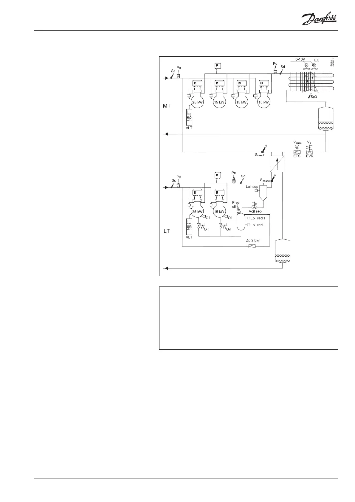
Refrigerating plant example
We have decided to describe the setup by means of
an example comprising a MT compressor group, a LT
compressor group and a cascade heat exchanger.
The example is the same as the one given in the
"Design" section, i.e. the controller is an AK-PC 783 +
extension modules.
There can be both an external and internal main switch as a setting. Both must be
“ON” before any adjustment is made.
Warning
The main switch will stop all regulations. In the event of temperature increases,
there is a risk of loss of lling.
Compressor Group
• MT circuit and LT circuit
• Refrigerant MT=134a. LT=CO
2
(R744)
• 4 and 2 compressors with "cyclic" operation
• First compressor is speed controlled
• Safety monitoring of each compressor
• Common high-pressure monitoring in each circuit
• T0-MT set point = -10°C, T0-LT = -30°C
• P0 optimisation on MT
• Oil management of each LT compressor
• Pulse reset for stopped compressor (lack of oil)
Condenser:
• Fans with EC motors, speed controlled
• Pc-MT regulates ooating based on temperature
sensor Sc3
Cascade exchanger
• Control sensor =Scasc3, Scacs 2, P0-MT, Pc-LT
• Valves = Stepper valve ETS and Solenoid valve EVR
Receivers:
• Control of pressure in oil receiver
Safety functions:
• Monitoring of Po, Pc, Sd and superheat in suction
line
• Monitoring of low and high level in oil receiver