If [No Operation] is selected in
par. 5-12 Terminal 27 Digital Input
, no connection to +24 V on terminal 27 is necessary to enable start.
If [Coast Inverse] (factory default value) is selected in
par. 5-12 Terminal 27 Digital Input
, a connection to +24V is necessary to enable start.
Select [Changes Made] to get information about:
• the last 10 changes. Use the up/down navigation keys to scroll between the last 10 changed parameters.
• the changes made since factory setting.
Select [Loggings] to get information about the display line read-outs. The information is shown as graphs.
Only display parameters selected in par. 0-20 and par. 0-24 can be viewed. It is possible to store up to 120 samples in the memory for later reference.
Efficient Parameter Set-up for ADAP-KOOL Applications
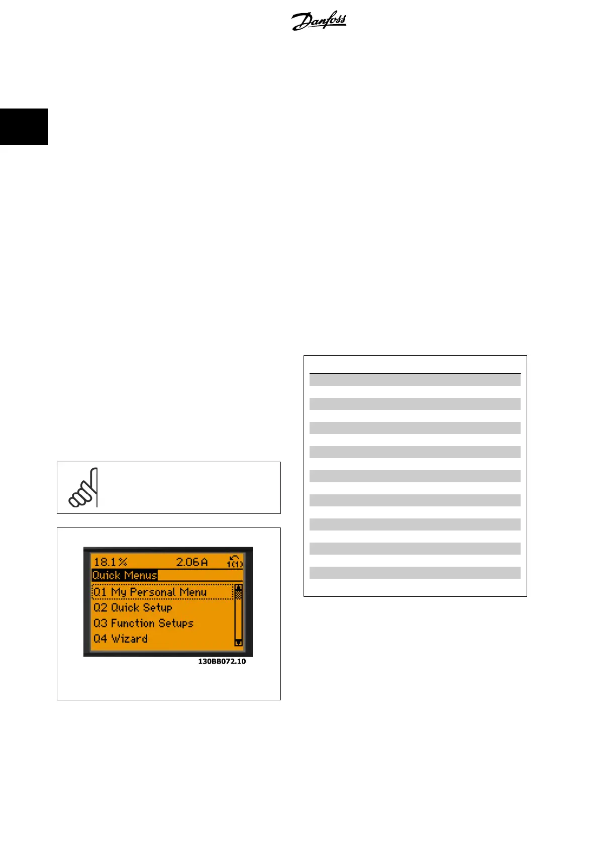
The parameters can easily be set up for the vast majority of the ADAP-KOOL applications only by using the [Quick Setup] option.
After pressing [Quick Menu], the different choices in the Quick Menu are listed. See also illustration 6.1 below and tables Q3-1 to Q3-4 in the follow-
ing
Function Setups
section.
Example of using the Quick Setup option
Assume you want to set the Ramp Down Time to 100 seconds
1. Select [Quick Setup]. The first
par. 0-01 Language
in Quick Set-
up appears
2.
Press [
▼
] repeatedly until
par. 3-42 Ramp 1 Ramp Down Time
appears with the default setting of 20 seconds
3. Press [OK]
4.
Use the [
◀
] button to highlight the 3rd digit before the comma
5.
Change '0' to '1' by using the [
▲
] button
6.
Use the [
▶
] button to highlight the digit '2'
7.
Change '2' to '0' with the [
▼
] button
8. Press [OK]
The new ramp-down time is now set to 100 seconds.
It is recommended to do the set-up in the order listed.
NB!
A complete description of the function is found in the
parameter sections of these Operating Instructions.
Illustration 2.6: Quick Menu view.
The Quick Setup menu gives access to the 13 most important setup pa-
rameters of the drive. After programming the drive will, in most cases be
ready for operation. The 13* Quick Setup parameters are shown in the
table below. A complete description of the function is given in the pa-
rameter description sections of this manual.
The display showing depends on choices made in parameter 0-02 and
0-03. The default setting of parameters 0-02 and 0-03 depends on which
region of the world the frequency converter is supplied to but can be re-
programmed as required.
Par.
Designation [Units]
0-01 Language
1-03 Torque characteristics
1-20 Motor Power [kW]
1-21 Motor Power* [HP]
1-22 Motor Voltage [V]
1-23 Motor Frequency [Hz]
1-24 Motor Current [A]
1-25 Motor Nominal Speed [RPM]
1-39 Motor Poles
4-12 Motor Speed Low Limit* [Hz]
4-14 Motor Speed High Limit* [Hz]
3-02 Minimum Reference
3-03 Maximum Reference
3-41 Ramp 1 Ramp up Time [s]
3-42 Ramp 1 Ramp down Time [s]
3-13 Reference Site
5-10 Terminal 18 Digital Input
1-29 Automatic Motor Adaptation (AMA)
Table 2.1: Quick Setup parameters
2 How to Programme ADAP-KOOL
®
Drive Programming Guide
24
MG.11.N1.02 - VLT
®
is a registered Danfoss trademark
2