34 | RS8EU702 |
Data
Supply voltage 230 V a.c. +10/-15 %. 5 VA, 50/60 Hz
Sensors
S6, S6B: Pt 1000
S3, S4, S5, , S5B: Pt 1000 or PTC 1000 ohm
(All 4 must be of the same type)
Accuracy
Measuring range -60 to +120°C
Controller
±1 K below -35°C
±0.5 K between -35 to +25°C
±1 K above +25°C
Pt 1000 sensor
±0.3 K at 0°C
±0.005 K per grad
Display LED, 3-digits
External display EKA 163B or 164B. (any EKA 163A or 164A)
Digital inputs
DI1, DI2
Signal from contact functions
Requirements to contacts: Gold plating
Cable length must be max. 15 m
Use auxiliary relays when the cable is longer
Digital input DI3 230 V a.c.
Electrical con-
nection cable
Max.1.5 mm
2
multi-core cable
Solid state
output
DO1
(for coil)
Max. 240 V a.c. , Min. 28 V a.c.
Max. 0.5 A
Leak < 1 mA
Max. 1 pcs. coil
Relays*
CE
(250 V a.c.)
DO3, DO4 4 (3) A
DO2, DO5, DO6 4 (3) A
Environments
0 to +55°C, During operations
-40 to +70°C, During transport
20 - 80% Rh, not condensed
No shock inuence / vibrations
Density IP 20
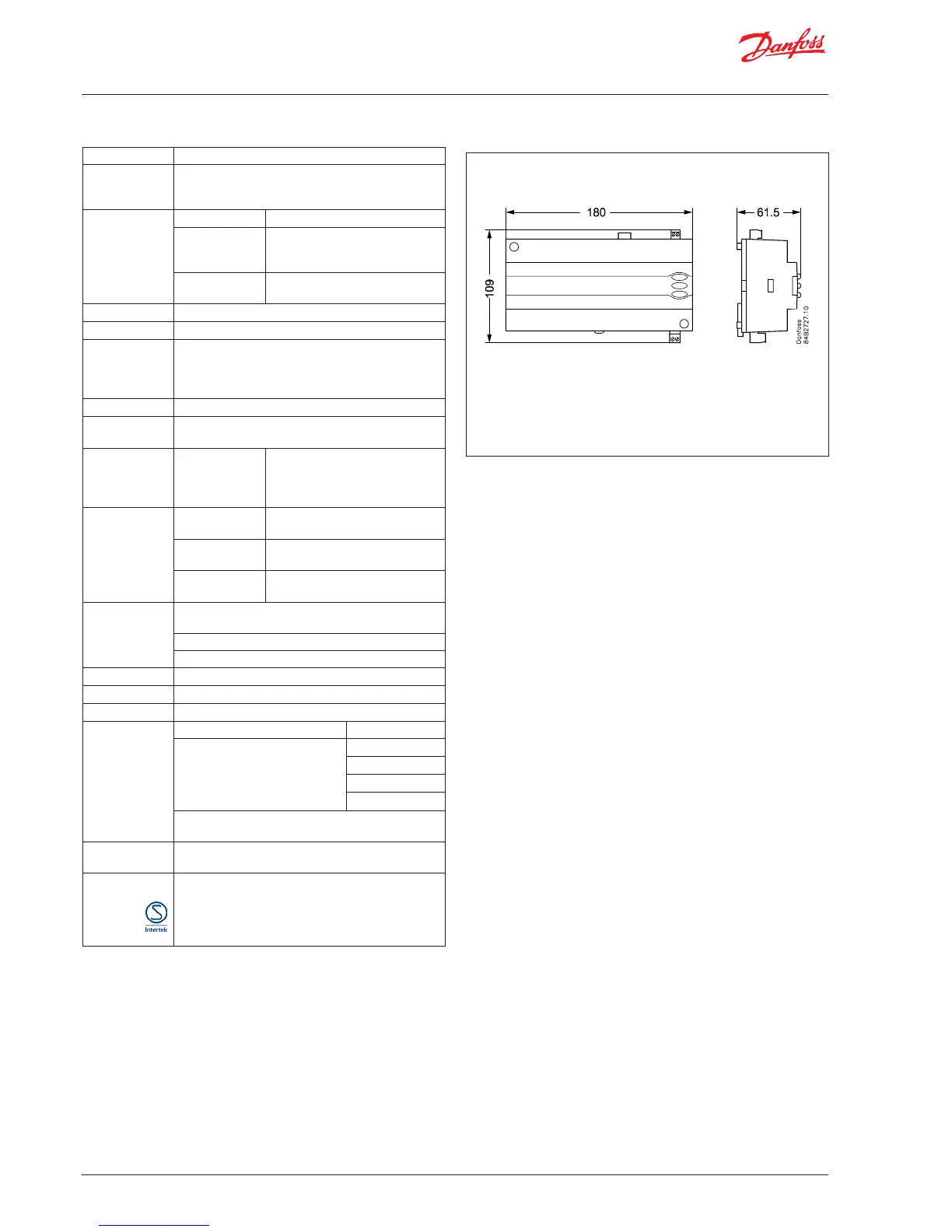
Mounting DIN-rail or wall
Weight 0.4 Kg
Data
communication
Fixed / Build-in MODBUS
Extension options
LON RS485
DANBUSS
TCP/IP (OEM)
MODBUS
The controller cannot be hooked up with a monitor-
ing unit type m2.
Power reserve
for the clock
4 hours
Approvals
EU Low Voltage Directive and EMC demands re CE-
marking complied with
LVD tested acc. EN 60730-1 and EN 60730-2-9, A1, A2
EMC tested acc. EN 61000-6-2 and EN 61000-6-3
Relays are tested acc. to IEC 60079-15
* DO3 and DO4 are 16 A relays. DO2, DO5 and DO6 are 8 A relays. Max. load must be observed.
Capacitive load
The relays cannot be used for the direct connection of capacitive loads such as LEDs and on/o
control of EC motors.
All loads with a switch mode power supply must be connected with a suitable contactor or simi-
lar.

 Loading...