Comp. o time when sensor fault
c87 1 0 min 240 min 30
Defrost
Defrost method: 0=O, 1= EL, 2= Gas, 3 = Brine
d01 1 1 1 1 1 1 1 1 1 0/O 3/bri 1/EL
Defrost stop temperature
d02 1 1 1 1 1 1 1 1 1 0°C 50°C 6
Interval between defrost starts
d03 1 1 1 1 1 1 1 1 1 0 hrs/O 240 hrs 8
Max. defrost duration
d04 1 1 1 1 1 1 1 1 1 0 min. 360 min. 45
Displacement of time on cutin of defrost at start-up
d05 1 1 1 1 1 1 1 1 1 0 min. 240 min. 0
Drip o time
d06 1 1 1 1 1 1 1 1 1 0 min. 60 min. 0
Delay for fan start after defrost
d07 1 1 1 1 1 1 1 1 1 0 min. 60 min. 0
Fan start temperature
d08 1 1 1 1 1 1 1 1 1 -50 °C 0 °C -5
Fan cutin during defrost
0: stopped
1: Running
2: Running during pump down and defrost
d09 1 1 1 1 1 1 1 1 1 0 2 1
Defrost sensor: 0 =Stop on time, 1=S5, 2=S4, 3=
(Application 1-5 and 7: Both S5A and S6A.
Application 6 and 8: individual S5A and S5B)
d10 1 1 1 1 1 1 1 1 1 0 3 0
Pump down delay
d16 1 1 1 1 1 1 1 1 1 0 min. 60 min. 0
Drain delay (used at hot gas defrost only)
d17 1 0 min. 60 min. 0
Max. aggregate refrigeration time between two defrosts
d18 1 1 1 1 1 1 1 1 1 0 hrs 48 hrs 0/OFF
Heat in drip tray. Time from defrosting stops to heating in
the drip tray is switched o
d20 1 0 min. 240 min. 30
Delay time before opening hot gas valve
d23 1 0 min 60 min 0
Rail heat during defrost
0: o
1: on
2: Pulsing
d27 1 1 1 1 0 2 2
Defrost stop temp. thermostat band 2
d28 1 0°C 50°C 6
Max. defrost duration thermostat band 2
d29 1 0 min 360 min 45
Regulation parameter for refrigeration
Period time at PWM n63 1 1 1 1 1 1 1 1 1 30 sec. 900 sec. 300
Max. opening degree at PWM n64 1 1 1 1 1 1 1 1 1 0% 100% 100
Min. opening degree at PWM n65 1 1 1 1 1 1 1 1 1 0% 90% 0
Expert setting. Windup at PWM n66 1 1 1 1 1 1 1 1 1 0.2 1.0 1.0
Expert setting. Kp at PWM n67 1 1 1 1 1 1 1 1 1 0.5 10.0 4.0
Expert setting. Tn at PWM n68 1 1 1 1 1 1 1 1 1 60 sec 1800 sec 300
Fan
Fan stop temperature (S5)
F04 1 1 1 1 1 1 1 1 1 -50°C 50°C 50
Pulse operation on fans: 0=No pulse operation, 1=At
thermostat cuts out only, 2= Only at thermostat cut outs
during night operation
F05 1 1 1 1 1 1 1 1 1 0 2 0
Period time for fan pulsation (on-time + o-time)
F06 1 1 1 1 1 1 1 1 1 1 min. 30 min. 5
On-time in % of period time
F07 1 1 1 1 1 1 1 1 1 0 % 100 % 100
Real time clock
Six start times for defrost.
Setting of hours.
0=OFF
t01 -
t06
1 1 1 1 1 1 1 1 1 0 hrs 23 hrs 0
Six start times for defrost.
Setting of minutes.
0=OFF
t11 -
t16
1 1 1 1 1 1 1 1 1 0 min. 59 min. 0
Clock - Setting of hours
t07 1 1 1 1 1 1 1 1 1 0 hrs 23 hrs 0
Clock - Setting of minute
t08 1 1 1 1 1 1 1 1 1 0 min. 59 min. 0
Clock - Setting of date
t45 1 1 1 1 1 1 1 1 1 1 day 31 day 1
Clock - Setting of month
t46 1 1 1 1 1 1 1 1 1 1 mon. 12 mon. 1
Clock - Setting of year
t47 1 1 1 1 1 1 1 1 1 0 year 99 year 0
Miscellaneous
Delay of output signals after start-up
o01 1 1 1 1 1 1 1 1 1 0 sec 600 sec 5
Input signal on DI1. Function:
0=not used. 1=status on DI1. 2=door function with alarm
when open. 3=door alarm when open. 4=defrost start (pulse-
signal). 5=ext.main switch. 6=night operation 7=Thermostat
band changeover (activate r21). 8=alarm function when
closed. 9=alarm function when open. 10=case cleaning (pulse
signal). 11=forced cooling at hot gas defrost, 12=night cover.
15=application shutdown
o02 1 1 1 1 1 1 1 1 1 0 15 0
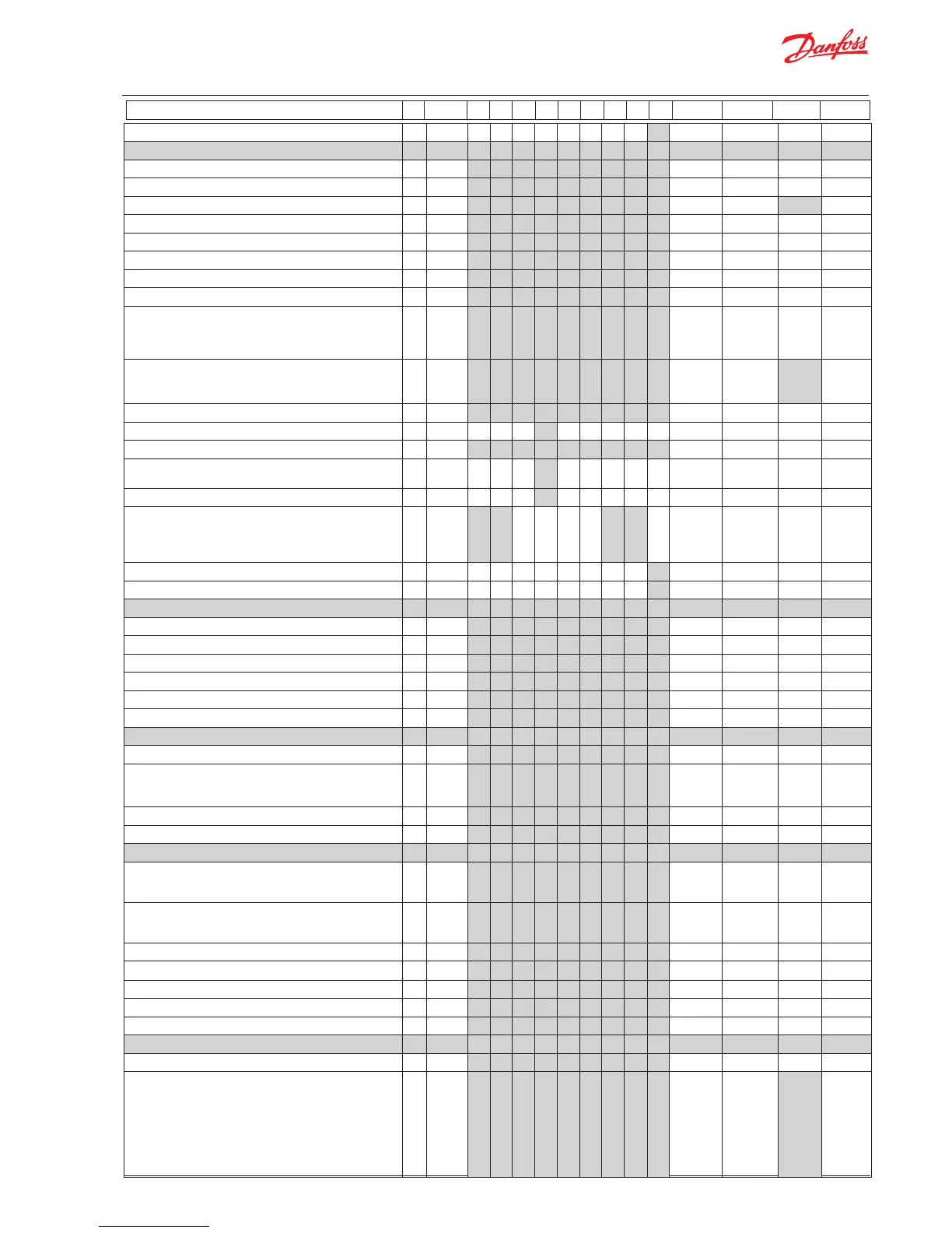
Continued code 1 2 3 4 5 6 7 8 9 Min. Max. Fac. Actual

 Loading...