AK-CC 550A Manual RS8FS402 © Danfoss 2016-03 29
Defrost sensor: 0 =Stop on time, 1=S5, 2=S4, 3=Sx
(Application 1-8 and 10: both S5 and S6.
Application 9: S5 and S5B)
d10 1 1 1 1 1 1 1 1 1 1 0 3 0
Pump down delay
d16 1 1 1 1 1 1 1 1 1 1 0 min. 60 min. 0
Drain delay (used at hot gas defrost only) d17 1 0 min. 60 min. 0
Max. aggregate refrigeration time between two defrosts
d18 1 1 1 1 1 1 1 1 1 1 0 hrs 48 hrs 0/OFF
Heat in drip tray. Time from defrosting stops to heating
in the drip tray is switched o
d20 1 0 min. 240 min. 30
Adaptive defrost:
0=not active, 1=monitoring only, 2=skip allowed day,
3=skip allowed both day and night, 4=own assessment
+ all schedules
d21 1 1 1 1 1 1 1 1 1 1 0 4 0
Time delay before opening of hot gas valve d23 1 0 min 60 min 0
Rail heat during defrost
0=o. 1=on. 2=Pulsating
d27 1 1 1 1 1 1 1 0 2 2
Injection control function
Max. value of superheat reference
n09 1 1 1 1 1 1 1 1 1 1 2°C 20°C 12
Min. value of superheat reference
n10 1 1 1 1 1 1 1 1 1 1 2°C 20°C 3
MOP temperature. O if MOP temp. = 15.0 °C n11 1 1 1 1 1 1 1 1 1 1 -50°C 15°C 15
Period time of AKV pulsation
Only for trained personnel
n13 1 1 1 1 1 1 1 1 1 1 3 sec 6 sec 6
Fan
Fan stop temperature (S5)
F04 1 1 1 1 1 1 1 1 1 1 -50°C 50°C 50
Pulse operation on fans: 0=No pulse operation, 1=At
thermostat cuts out only, 2= Only at thermostat cut
outs during night operation
F05 1 1 1 1 1 1 1 1 1 1 0 2 0
Period time for fan pulsation (on-time + o-time) F06 1 1 1 1 1 1 1 1 1 1 1 min. 30 min. 5
On-time in % of period time F07 1 1 1 1 1 1 1 1 1 1 0 % 100 % 100
Real time clock
Six start times for defrost.
Setting of hours.
0=OFF
t01 -
t06
1 1 1 1 1 1 1 1 1 1 0 hrs 23 hrs 0
Six start times for defrost.
Setting of minutes.
0=OFF
t11 -
t16
1 1 1 1 1 1 1 1 1 1 0 min. 59 min. 0
Clock - Setting of hours
t07 1 1 1 1 1 1 1 1 1 1 0 hrs 23 hrs 0
Clock - Setting of minute
t08 1 1 1 1 1 1 1 1 1 1 0 min. 59 min. 0
Clock - Setting of date
t45 1 1 1 1 1 1 1 1 1 1 1 day 31 day 1
Clock - Setting of month
t46 1 1 1 1 1 1 1 1 1 1 1 mon. 12 mon. 1
Clock - Setting of year
t47 1 1 1 1 1 1 1 1 1 1 0 year 99 year 0
Miscellaneous
Delay of output signals after start-up
o01 1 1 1 1 1 1 1 1 1 1 0 sec 600 sec 5
Input signal on DI1. Function:
0=not used. 1=status on DI1. 2=door function with alarm
when open. 3=door alarm when open. 4=defrost start
(pulse-signal). 5=ext.main switch. 6=night operation
7=thermostat band changeover (activate r21). 8=alarm
function when closed. 9=alarm function when open.
10=Appliance cleaning (pulse signal). 11=forced cooling at
hot gas defrost, 12=night cover. 15=case shut down
o02 1 1 1 1 1 1 1 1 1 1 0 15 0
Network address
o03 1 1 1 1 1 1 1 1 1 1 0 240 0
On/O switch (Service Pin message)
IMPORTANT! o61 must be set prior to o04
(used at LON 485 and DANBUSS only)
o04 1 1 1 1 1 1 1 1 1 1 0/O 1/On 0/O
Access code 1 (all settings)
o05 1 1 1 1 1 1 1 1 1 1 0 100 0
Used sensor type : 0=Pt1000, 1=Ptc1000, o06 1 1 1 1 1 1 1 1 1 1 0/Pt 1/Ptc 0/Pt
Readout of software version o08 1 1 1 1 1 1 1 1 1 1
Max hold time after coordinated defrost
o16 1 1 1 1 1 1 1 1 1 1 0 min. 360 min. 20
Select signal for display view. S4% (100%=S4, 0%=S3)
o17 1 1 1 1 1 1 1 1 0 % 100 % 100
Pressure transmitter working range – min. value
o20 1 1 1 1 1 1 1 1 1 1 -1 bar 5 bar -1
Pressure transmitter working range – max. value
o21 1 1 1 1 1 1 1 1 1 1 6 bar 200 bar 12
Refrigerant setting:
1=R12. 2=R22. 3=R134a. 4=R502. 5=R717. 6=R13.
7=R13b1. 8=R23. 9=R500. 10=R503. 11=R114.
12=R142b. 13=User dened. 14=R32. 15=R227.
16=R401A. 17=R507. 18=R402A. 19=R404A. 20=R407C.
21=R407A. 22=R407B. 23=R410A. 24=R170. 25=R290.
26=R600. 27=R600a. 28=R744. 29=R1270. 30=R417A.
31=R422A. 32=R413A. 33=R422D. 34=R427A. 35=R438A.
36=R513A. 37=R407F. 38=R1234ze. 39=R1234yf.
o30 1 1 1 1 1 1 1 1 1 1 0 39 0
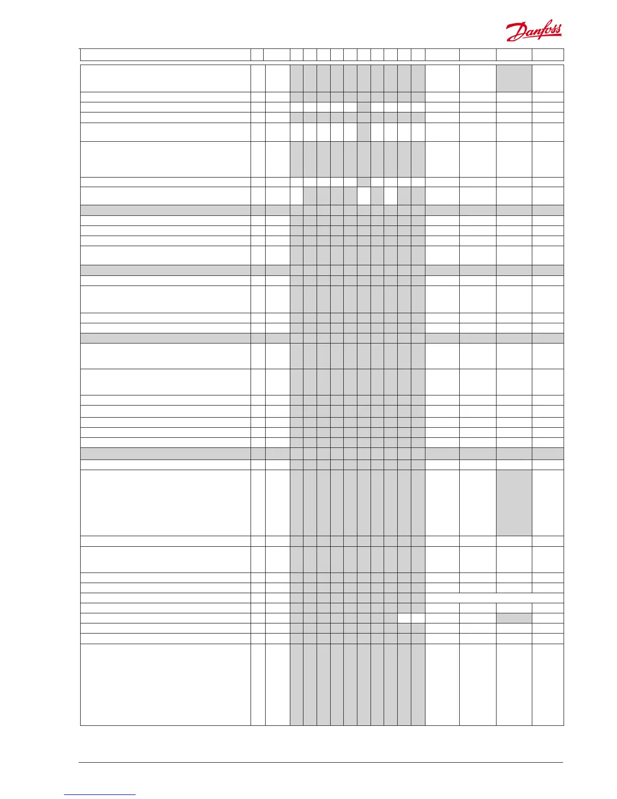
Continued Code 1 2 3 4 5 6 7 8 9 10 Min. Max. Fac. Actual