30 Manual RS8FS402 © Danfoss 2016-03 AK-CC 550A
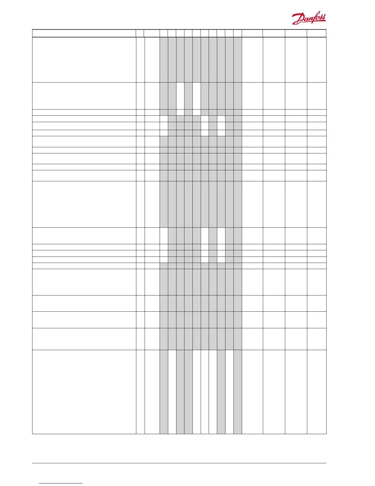
Continued Code 1 2 3 4 5 6 7 8 9 10 Min. Max. Fac. Actual
Input signal on DI2. Function:
(0=not used. 1=status on DI2. 2=door function with alarm
when open. 3=door alarm when open. 4=defrost start
(pulse-signal). 5=ext. main switch 6=night operation
7=thermostat band changeover (activate r21). 8=alarm
function when closed. 9=alarm function when open.
10=Appliance cleaning (pulse signal). 11=forced cooling at
hot gas defrost.). 12=night cover, 13=coordinated defrost).
15=case shut down
o37 1 1 1 1 1 1 1 1 1 1 0 15 0
Conguration of light function: 1=Light follows day /night
operation, 2=Light control via data communication
via ‘o39’, 3=Light control with a DI-input, 4=As "2", but
light switch on and night cover will open if the network
cut out for more than 15 minutes.
o38 1 1 1 1 1 1 1 1 1 4 1
Activation of light relay (only if o38=2) On=light o39 1 1 1 1 1 1 1 1 0/O 1/On 0/O
Rail heat On time during day operations
o41 1 1 1 1 1 1 1 0 % 100 % 100
Rail heat On time during night operations
o42 1 1 1 1 1 1 1 0 % 100 % 100
Rail heat period time (On time + O time)
o43 1 1 1 1 1 1 1 6 min. 60 min. 10
Appliance cleaning. 0=no Appliance cleaning. 1=Fans only.
2=All output O.
*** o46 1 1 1 1 1 1 1 1 1 1 0 2 0
Selection of EL diagram. See overview page 12 and 13
* o61 1 1 1 1 1 1 1 1 1 1 1 10 1
Download a set of predetermined settings. See overview
page 27.
* o62 1 1 1 1 1 1 1 1 1 1 0 6 0
Access code 2 (partial access)
*** o64 1 1 1 1 1 1 1 1 1 1 0 100 0
Replace the controllers factory settings with the present
settings
o67 1 1 1 1 1 1 1 1 1 1 0/O 1/On 0/O
Input signal on DI3. Function: (high voltage input)
(0=not used. 1=status on DI2. 2=door function with alarm
when open. 3=door alarm when open. 4=defrost start
(pulse-signal). 5=ext. main switch 6=night operation,
7=thermostat band changeover (activate r21). 8=Not
used. 9=Not used. 10=Appliance cleaning (pulse signal).
11=forced cooling at hot gas defrost, 12=night cover.
13=Not used. 14=Refrigeration stopped (forced
closing)). 15=case shut down
o84 1 1 1 1 1 1 1 1 1 1 0 15 0
Rail heat control
0=not used, 1=pulse control with timer function (o41
and o42), 2=pulse control with dew point function
o85 1 1 1 1 1 1 1 0 2 0
Dew point value where the rail heat is minimum o86 1 1 1 1 1 1 1 -10°C 50°C 8
Dew point value where the rail heat is 100% on o87 1 1 1 1 1 1 1 -9°C 50°C 17
Lowest permitted rail heat eect in % o88 1 1 1 1 1 1 1 0 % 100 % 30
Time delay from "open door” refrigeration is started o89 1 1 1 1 1 1 1 1 1 1 0 min. 240 min. 30
Fan operation at stopped cooling (forced closing):
0= Stopped (defrost allowed)
1= Running (defrost allowed)
2= Stopped (defrost not allowed)
3= Running (defrost not allowed)
o90 1 1 1 1 1 1 1 1 1 1
0 3 1
1=defrost stop temperature, 2=S6 temperature,
3=S5_B temperature (application 9), 4=S3B (application
10)
o92 1 1 1 1 1 1 1 1 1 1 1 4 1
Display of temperature
1= u56 Air temperature
2= u36 product temperature
o97 1 1 1 1 1 1 1 1 1 1 1 2 1
Light and night blinds dened
0: Light is switch o and night blind is open when the
main switch is o
1: Light and night blind is independent of main switch
o98 1 1 1 1 1 1 1 1 1 1 0 1 0
Conguration of alarm relay
The alarm relay will be activated upon an alarm signal
from the following groups:
1 - High temperature alarms
2 - Low temperature alarms
4 - Sensor error
8 - Digital input enabled for alarm
16 - Defrosting alarms
32 - Miscellaneous
64 - Injection alarms
The groups that are to activate the alarm relay must be
set by using a numerical value which is the sum of the
groups that must be activated.
(E.g.: a value of 5 will activate all high temperature
alarms and all sensor error and 0 will cancel the relay
function).
P41 1 1 1 1 1 0 127 111
 Loading...


