130 Capacity controller RS8HE202 © Danfoss 2017-07 AK-PC 781A
The speed-regulated compressor is used to fill the capacity gaps
between the one-step compressors.
Example:
Increasing capacity:
- The speed-regulated compressor starts when the desired
capacity equals the start speed
- The following one-step compressor with the smallest number
of operating hours cut in when the speed-regulated compres-
sor is running at full speed (90 Hz)
-When a one-step compressor cuts in, the speed-regulated com-
pressor reduces speed (40 Hz) equivalent to the capacity of the
one-step compressor.
Decreasing capacity:
- The following one-step compressors with the most operating
hours should be cut out when the speed-regulated compressor
reaches minimum speed (30 Hz)
- When a one-step compressor is cut out, the speed- regulated
compressor’s speed increases (80 Hz), equivalent to the capac-
ity of the one-step compressor
- The speed-regulated compressor is the last compressor to be
cut out when the preconditions for this are fulfilled.
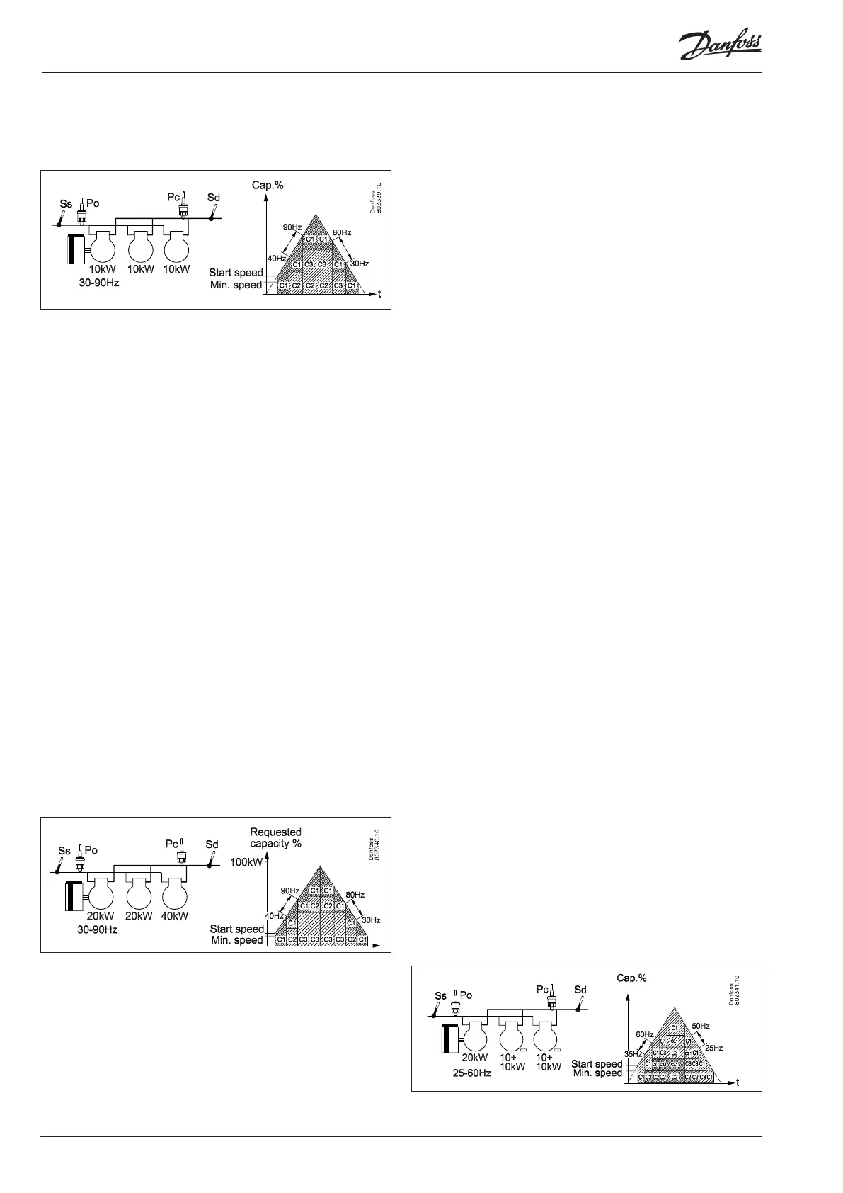
Best fit - example:
Here, at least two of the one-step compressors are of different
sizes.
The speed-regulated compressor is always the first to start and
last to stop.
The capacity distributor cuts in and cuts out the one-step com-
pressors in order to achieve the best possible capacity fit (least
possible capacity jump)
The speed-regulated compressor is used to fill out the capacity
gaps between the one-step compressors.
Example:
Increasing capacity:
- The speed-regulated compressor starts when the desired
capacity matches the start speed
- The smallest one-step compressor is cut in when the speed-
regulated compressor runs at full-speed (90 Hz).
- When the speed-regulated compressor again reaches max.
speed (90 Hz), the smallest one-step compressor is cut out (C2)
and the big one-step compressor (C3) is cut in.
- When the speed-regulated compressor again reaches max
speed (90 Hz), the smallest one-step compressor (C2) is cut in
again.
- When the one-step compressor is cut in, the speed is reduced
on the speed-regulated compressor (40 Hz) equivalent to the
capacity of the cut in capacity
Decreasing capacity:
- The small one-step compressor is cut out when the speed-regu-
lated compressor has reached minimum speed (30 Hz)
- When the speed-regulated compressor again reaches minimum
speed (30 Hz), the smallest one-step compressor (C2) is cut out
and the big one-step compressor (C3) is cut in.
- When the speed-regulated compressor again reaches min.
speed (30 Hz), the large one-step compressor (C3) is cut out
and the small one-step compressor (C2) is cut in again.
- When the speed-regulated compressor again reaches min.
speed (30 Hz), the small one-step compressor (C2) is cut in.
- The speed-regulated compressor is the last compressor to be
cut out when the requirements for this are fulfilled.
- When the one-step compressor’s capacity is cut out, the speed-
regulated compressor increases speed (80 Hz) equivalent to
the cut out capacity.
Compressor application 6 – 1 x Speed + unloader
The controller can operate one speed-regulated compressor com-
bined with several capacity-regulated compressors of the same
size and with the same number of unloaders.
The advantage of this combination is that the variable part of the
speed-regulated compressor only needs to be large enough to
cover the following unload valves in order to achieve a capacity
curve without gaps.
Preconditions for using this compressor application are:
• A single speed-regulated compressor that can be of a different
size than the following compressors
• The capacity-regulated compressors are the same size and have
the same number of unload valves (max. 3)
• The main step on the capacity-regulated compressors are the
same size
• The main step and the unload valves can be different sizes, i.e.
50%, 25% and 25%.
This compressor combination can be handled in the following
coupling patterns:
• Cyclical
Handling the speed-regulating compressor.
For further information on the general handling of the speed-
regulated compressor, refer to section "Power pack types".
Cyclical operation - example
The speed-regulated compressor is always the first to start and
last to stop.
The capacity-regulated compressors are cut in and cut out in ac-
cordance with the First-in-First-Out principle in order to equalise
operating hours
The speed-regulated compressor is used to fill the ca-
pacity gaps between the unload valves/main steps.