AK-PC 781A Capacity controller RS8HE202 © Danfoss 2017-07 131
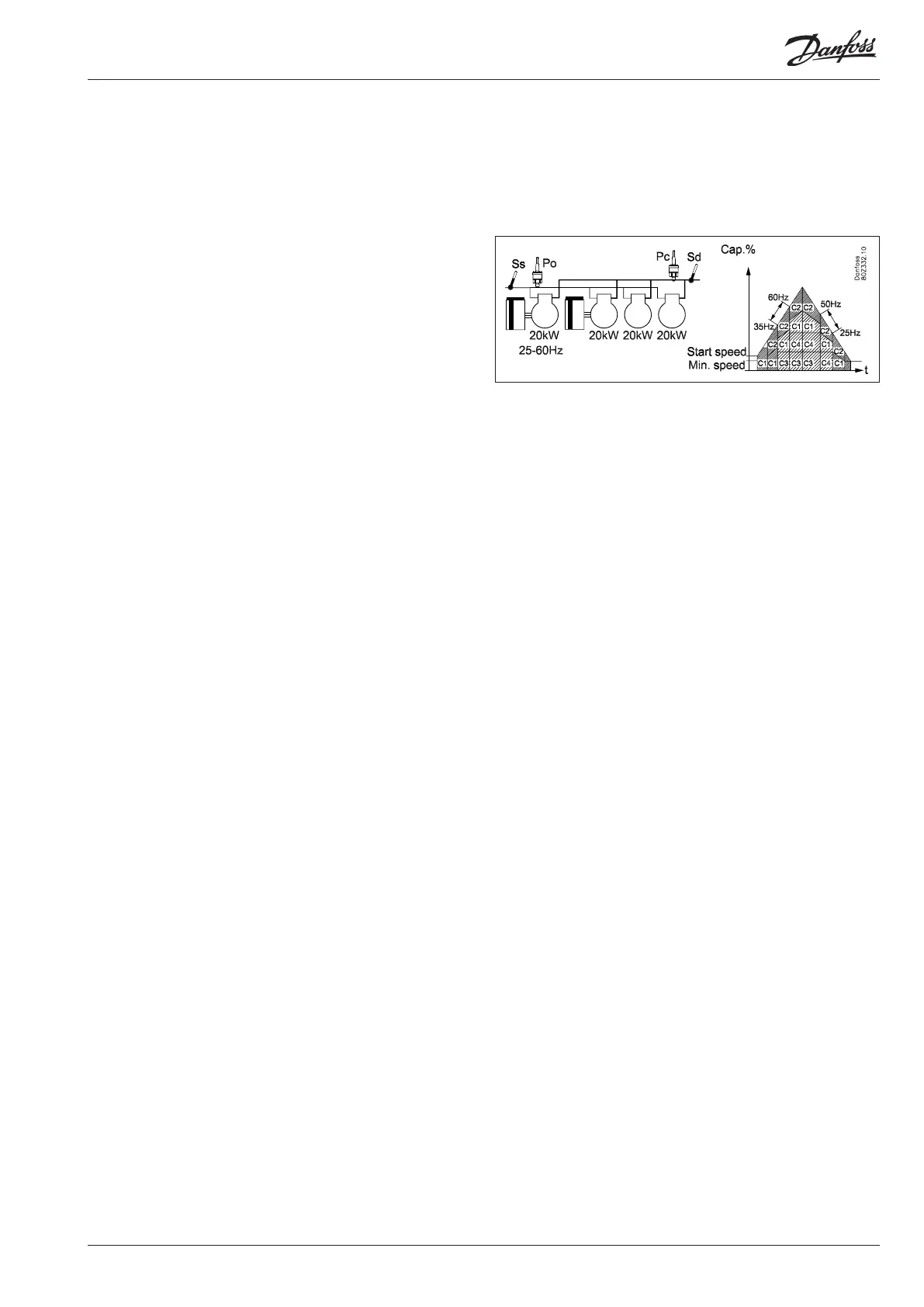
Increasing capacity:
- The speed-regulated compressor starts when the desired
capacity matches the start speed
- The main step on the capacity-regulated compressor with
fewest operating hours (C1) is cut in when the speed-regulated
compressor runs at full speed (60 Hz)
- The unload valves are cut in gradually as the speed-regulated
compressor again reaches max. speed (60 Hz)
- The main step on the last capacity-regulated compressor (C2)
is cut in when the speed-regulated compressor again reaches
max. speed (60 Hz)
- The unload valves are cut in gradually as the speed-regulated
compressor again reaches max. speed (60 Hz)
- When the main step or unload valves are cut in, the speed is re-
duced on the speed-regulated compressor (35 Hz) is equivalent
to the capacity of the cut in capacity.
Decreasing capacity:
- The capacity-regulated compressor with the most operating
hours (C2) cuts out an unload valve when the speed-regulated
compressor has reached min. speed (25 Hz)
- When the speed-regulated compressor again reaches min.
speed (25 Hz), the unload valve is cut out on the next capacity-
regulated compressor (C3)
- When the speed-regulated compressor again reaches min.
speed (25 Hz), the main step is cut out on the capacity-regulat-
ed compressor with the most operating hours (C2)
- When the speed-regulated compressor again reaches min.
speed (25 Hz), the main step is cut out on the last capacity-
regulated compressor (C3)
- The speed-regulated compressor is the last compressor that is
cut out when the conditions for this are fulfilled
- When the main step or unload valves are cut out, the speed of
the speed-regulated compressor increases (50 Hz) to equiva-
lent to the cut out capacity
Compressor application 7 – 2 x Speed + single
The controller can control two speed-regulated compressors com-
bined with several one-step compressors that may be the same or
different in size (depending on the selected coupling pattern).
The advantage of using two speed-regulated compressors is that
it is then possible to reach a very low capacity, which is an advan-
tage with low loads while at the same time a very high variable
regulating range is possible.
Preconditions for using this compressor application are:
• Two speed-regulated compressors which can be of a different
size than the following one-step compressors
• The speed-regulated compressors can be the same or different
sizes (depending on the choice of coupling pattern)
• The same frequency band for both speed-regulated compressors
• One-step compressors of the same or different sizes (depending
on the choice of coupling pattern)
This compressor combination can be handled in accordance with
the following coupling patterns:
• Cyclical
• Best fit
Handling the speed-regulated compressor.
For more information on the general handling of the speed-regu-
lated compressors, refer to section "Power pack types".
Cyclical operation - example
Here the speed-regulated compressors are the same size
The one-step compressors should also be the same size.
The speed-regulated compressor is always the first to start and the
last to stop.
The other compressors cut in and cut out in accordance with the
operating time (First-In-First-Out principle).
The speed-regulated compressor is used to fill the capacity gaps
between the following one-step compressors.
Example:
Increasing capacity:
- The speed-regulated compressor with the least operating hours
(C1) starts when the desired capacity equals the start speed
- The following speed-regulated compressor C2 is cut in when
the first speed-regulated compressor (C1) has reached max.
speed (60 Hz) so that the compressors run in parallel.
- When the two speed-regulated compressors reach full speed
(60 Hz) the one-step compressor with the fewest operating
hours is cut in (C3)
- When the two speed-regulated compressors again reach full
speed (60 Hz) the last one-step compressor cuts in (C4)
- When one-step compressors are cut in , the speed is reduced
on the speed-regulated compressor (35 Hz) equivalent to the
cut in capacity.
Decreasing capacity:
- The one-step compressor with the most operating time (C3)
is cut out when the speed-regulated compressor reaches min
speed (25 Hz)
- When the two speed-regulated compressors again reach min
speed (25 Hz), the last one-step compressor is cut out (C4)
- When the two speed-regulated compressors again reach min
speed (25 Hz), the speed-regulated compressor with the most
operating hours is cut out (C1)
- The last speed-regulated compressor (C2) is cut out when the
requirements for this are fulfilled
- When one-step compressors are cut out, the speed-regulated
compressors’ speed increases (50 Hz), equivalent to the cut out
capacity.
Best fit - examples
Here, either the two speed-regulated compressors are of different
sizes, or the following one-step compressors are of different sizes.
The speed-regulated compressors are always the first to start and
the last to stop.
The capacity distributor cuts in and cuts out both speed-regulated
and one-step compressors in order to reach the best possible
capacity adjustment (least possible capacity jump).