70 | 180R9346 | AQ240486503020en-001702 © Danfoss | 2023.03
Operation guide Installation, Operation and Maintenance APP 53-92 pumps
Operating/Assembly instructions
Type HEW, HEW Compact and HEW-ZS
Sheet:
of 22
Please observe protection
note ISO 16016.
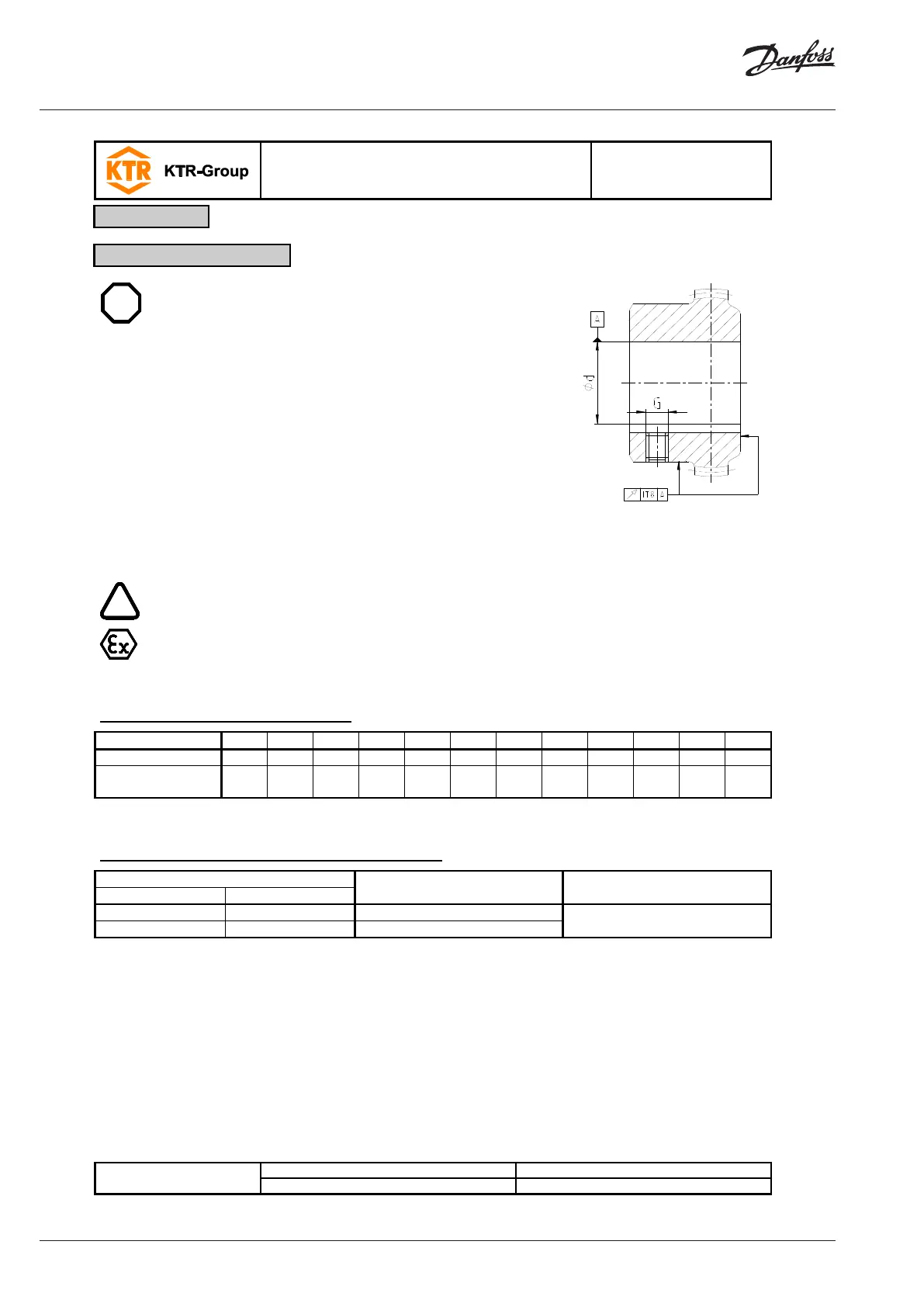
The maximum permissible bore diameters d (see table 1 to 5
in chapter 1 - technical data) must not be exceeded. If these
figures are disregarded, the coupling may tear. Rotating par-
ticles may cause danger to life.
Bores on the hubs/coupling flange machined by the customer
have to observe concentricity or axial runout (see illustration
12).
Please make absolutely sure to observe the figures for Ø d
max
.
Carefully align the hub or coupling flange when the finish
bores are drilled.
Provide for a setscrew according to DIN EN ISO 4029 with a
cup point or an end plate to fasten the hub or coupling flange
axially.
Illustration 12: Concentricity and axial
The customer bears the sole responsibility for all machining processes performed subse-
quently on unbored or pilot bored as well as finish machined coupling components and
spare parts. KTR does not assume any warranty claims resulting from insufficient rema-
chining.
Table 7: Setscrews DIN EN ISO 4029
Tightening torque
T
A
[Nm]
10 10 17 17 17 40 80 80 80 80 140 140
Table 8: Recommended fit pairs acc. to DIN 748/1
Shaft tolerance Bore tolerance
If a feather keyway is intended to be used in the hub, it should correspond to the tolerance ISO JS9 (KTR stand-
ard) with normal operating conditions or ISO P9 with difficult operating conditions (frequently alternating torsional
direction, shock loads, etc.).
The transmittable torque of the shaft-hub-connection must be reviewed by the customer and is subject to his re-
sponsibility.
4 Assembly
4.2 Advice for finish bore