Installation Guide CF-MC Master Controller
4
02/2013 VIUHK8C1 Danfoss Heating Solutions
1. Introduction
The CF-MC Master Controller is a part of the new trend-setting CF2
+
wireless hydronic oor heating
control system from Danfoss. Based on 2-way wireless communication technology CF2
+
oers high
transmission safety, easy wireless installation, a high level of individual room temperature control,
and thus optimal comfort and improved energy eciency.
The system has a variety of benecial features and easily accessed application functionalities. This
includes a CF-MC Master Controller with short-circuit protected outputs, regulation by Pulse Width
Modulation (PWM) principles, away function, separate relays for both pump and boiler control, self-
diagnostic program and error indication, wireless transmission (link) test possibility on each type of
Room Thermostat, easy wireless system access and extended functionality via the optional CF-RC
Remote Controller, and CF-RU Repeater Unit for extended wireless range.
2. CF2
+
System Overview (g. 1)
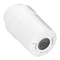
1a)
CF-MC Master Controller.
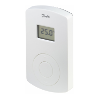
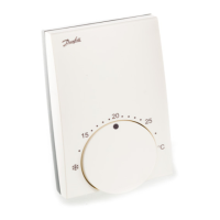
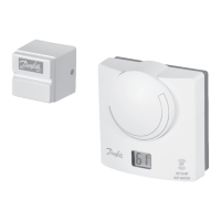
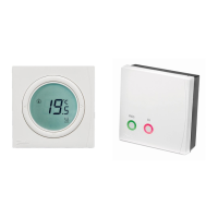
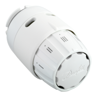
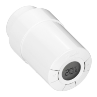
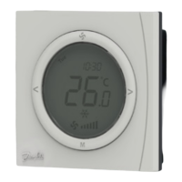
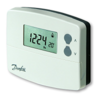
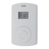
1b) CF-RS, -RP, -RD and -RF Room Thermostats.
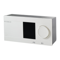
1c) CF-RC Remote Controller.
1d) CF-RU Repeater Unit.
1e) CF-DS Dew-point Sensor.
1f) CF-WR Wireless Relay.
1g) CF-EA External Antenna.
3. Functional Overview (g. 2)
Menu selection button.
Menu LEDs.
Output and conguration selection button.
OK button.
Output LEDs.
Output cable xing.
Relays for pump and boiler.
Input for heating/cooling (external ON/OFF switch).
Input for away function (8 °C) (external ON/OFF switch).
Input for PT1000 pipe sensor.
Front cover release.
External antenna connection.
4. Mounting and Installation Procedure (Sequential)
The wireless systems transmission range is sucient for most applications; however wireless signals
are weakened on the way from the CF-MC Master Controller to the Room Thermostats and each
building has dierent obstacles.
Checklist for optimal installation and best wireless signal strength (g. 3):
•No metal objects between the CF-MC Master Controller and the Room Thermostats.
•Wireless signal through walls on shortest possible diagonal distance.
•Optimise the wireless signal by installing a CF-RU Repeater Unit.
Note! Danfoss recommends that an installation plan is made before beginning the actual installation.
4.1 CF-MC Master Controller
Mount the CF-MC Master Controller in an horizontal upright position.
Wall:
•Remove the front cover (g. 4).
•Mount with screws and wall plugs (g. 5).
DIN-Rail:
•Mount DIN-rail parts (g. 6).
•Click on DIN-rail (g. 7).
•Release from DIN-rail (g. 8).
Important! Complete all the installations on the CF-MC Master Controller described below, before
connecting to a 230 V power supply!
 Loading...