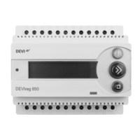
DEVIreg™ 850 IV
11Installation instruction
2�2 Placement
The DEVIreg™ 850 and power supply are designed for DIN rail mounting. When mount-
ing please be aware of the following conditions:
The DEVIreg™ 850 is designed and approved to operate in the temperature
range –10 °C to 40 °C.
The DEVIreg™ 850 is only IP20 protected, thus not water resistant.
The installer must ensure proper enclosure of the DEVIreg™ 850 according
to national standards (electrical safety).
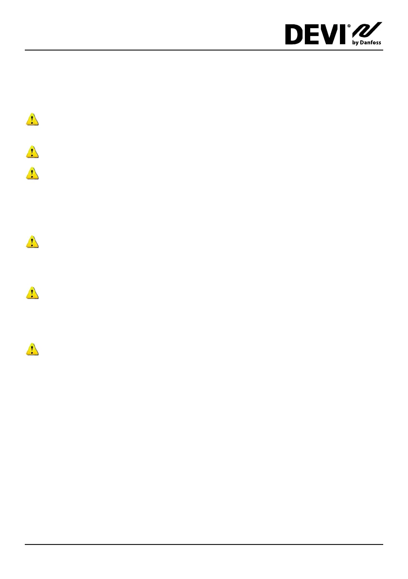
2�3 Connection steps for system
Only authorized personnel is allowed to install the DEVIreg™ 850.
When wiring up the DEVIreg™ 850 and sensors, please be aware of the following
conditions:
When the DEVIreg™ 850 is used in a dual system configuration, it is prefer-
able that each sensor bus (DEVIbus™) can be connected and disconnected
via switches. During the installation of a dual system, each system must be
connected one at a time.
Be aware of maximum allowable power drain from power supply to sensors.
Below is shown the recommended order of the installation. Please refer to figure A for
connection of DEVIreg™ 850 and refer to figure B–G for a guideline to connect the heat-
ing elements to DEVIreg™ 850.
1. Connect heating cables to the DEVIreg™ 850
• Please notice that a single system ALWAYS uses the System A output relay
• When using external power relay, please refer to the connection diagrams.
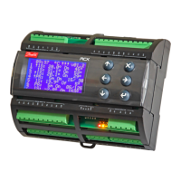
2. Connect the power supply to the DEVIreg™ 850
• Do not connect the power supply to mains yet
3. Connect sensors to the DEVIbus™
• When used as a dual system, only the sensors for System A can be connected.
For connection of System B please refer to chapter: “Installation of dual system”.
4. Connect the power supply to mains.