3
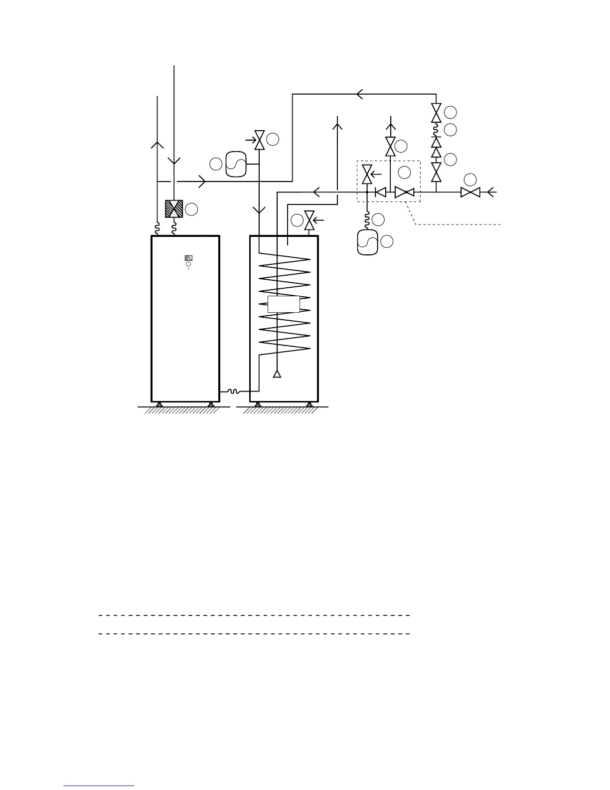
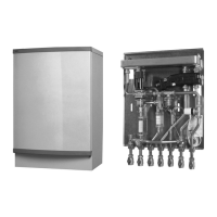
The principal installation solution of the unvented package on a DWH.Figure 5.
Position Name
1 Factory fitted combined Temperature and Pressure Relief Valve
*
2 Expansion Vessel
3 Flexible hose
5 Unvented manifold assembly: Pressure Reducing Valve, Safety Relief Valve,
Non-return Valve
6 Shut-off Valve
7 Double Check Valve with Shut-off Valve
8 Flexible hose
9 Safety Relief Valve
10 Expansion Vessel Heating System
11 Strainer
*
) The water heater tank in DWH is factory fitted with a Temperature and Pressure Relief Valve. The connec-
tion from this valve must not be used for other purposes other than discharge pipe connection. Please see
next page for Discharge Pipe Arrangement.
E
Note! No valve should be fitted between the safety relief valve and the storage cylinder.