The shown diagram is a fundamental and simplied example and
does not contain all components that are necessary in a system.
If the system you are about to install diers from the shown
diagram of a standard heating system, feel free to sketch an
outline for comparison. Adaptation of systems, see section 10.
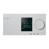
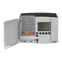
Circuit
indicator
Circuit
selector
Shift
button
Adjust-
ment
Controller
mode
List of components:
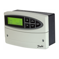
ECL Comfort 300
S1 Outdoor temperature sensor
S2 Room temperature sensor
S3 Flow temperature sensor, circuit I
S4 Return temperature sensor, circuit I
S5 DHW ow temperature sensor, circuit II
S6 DHW return temperature sensor, circuit II
P1 Circulation pump, heating, circuit I
P3 Circulation pump, DHW, circuit II
M1 Motorized control valve, circuit I
M2 Motorized control valve, circuit II
This guide is associated with ECL Card 087B4977
Installer:
By:
Date:
Controller mode
Manual operation (used only at maintenance
and service)
Scheduled operation
Constant comfort temperature
Constant setback temperature
Standby mode
Arrow buttons. Switch between the lines of the ECL
Card.
Shift button. Switches between temperatures,
changeover points etc.
Adjust temperatures and values etc.
Circuit selector for switching between the circuits.
Safety Note
To avoid injury of persons and damages to the device, it is absolutely
necessary to read and observe these instructions carefully.
Necessary assembly, start-up, and maintenance work must be performed by
qualied and authorized personnel only.
Display indications, controlled units, F66
 Loading...