Table 10: EKE 1D pinout
S3/S4 selectable via software
Analog inputs 0 – 5 V / Ratiometric pressure transmitter
External Reference signal
Power output for Ratiometric pressure transmitter 0 – 5V
NOTE:
• EKE 2U Backup power module is recommended to ensure closure of the electronic valves. in case of power failures
• If Dl1(On/O) switch is not used it must be short circuited
3.4 Cabling lengths for dierent connections
Considerations:
• The max. cable distance between the controller and the valve depends on many factors like shielded/unshielded
cable, the wire size used in the cable, the output power for the controller and EMC.
• Keep controller and sensor wiring well separated from mains wiring.
• Connecting sensors by wires more than the specied length may decrease the accuracy of measured values.
• Separate the sensor and digital input cables as much as possible (at least 10 cm) from the power cables to the
loads to avoid possible electromagnetic disturbance. Never lay power cables and probe cables in the same
conduits (including those in the electrical panels).
• For the CANbus cable, it is best to use 24 AWG shielded twisted-pair cable with a shunt capacitance of 16 pF/ft and
100 Ω impedance.
• The controller provides a communication interface which is connected to the RJ and CAN terminals.
• Terminal resistors 120 Ω for terminal devices are recommended at both ends of the bus (rst and last node)
Terminal resistance between H and R terminals.
Table 11: EKE controller supports the following max. cable length
Analog inputs (Current/Voltage)
• All valves are driven with a 24 V supply chopped to control the current (Current driver).
• The stepper motor is connected to the “Stepper Valve” terminals (see terminal assignment) with Danfoss M12
connection cable.
• To congure stepper motor valves other than Danfoss stepper motor valves, the correct valve parameters must be
set as described in the Valve conguration section (see the conguration section for details).
• The correct valve must be dened in “Valve conguration”, i.e., parameter I067.
Table 12: ETS Colibri / KVS Colibri/ ETS / KVS / CCM / CCMT / CTR
ETS Colibri® / KVS Colibri /
CCMT / CTR / CCM Pins
Table 13: ETS 6
© Danfoss | Climate Solutions | 2022.06 BC398828796060en-000101 | 13
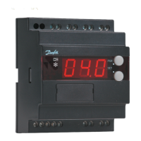
Superheat controller, Type EKE 1A, 1B, 1C, 1D