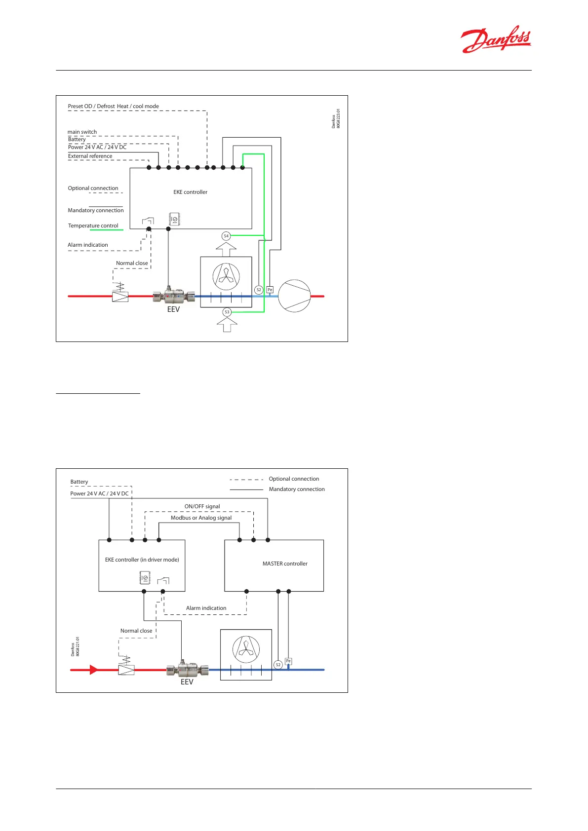
Figure 20: Temperature control application
Danfoss
80G8223.01
EEV
S4
Pe
S2
EKE controller
Preset OD /
Defrost
Heat / cool mode
Battery
Power 24 V AC / 24 V DC
External reference
Optional connection
Mandatory connection
Alarm indication
Temperature control
Normal close
main switch
S3
NOTE:
EKE1A cannot support thermostatic modes
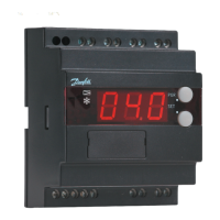
4.2 Driver Mode
A master is commanding the valve open degree to the EKE controller. The control signal can be fed for example by:
• Analog signal e.g., 0 – 10 V, a 0 – 20 mA
• Bus communication
Figure 21: EKE as Driver Mode
Pe
S2
Battery
Optional connection
Alarm indication
Normal close
Mandatory connection
ON/OFF signal
Modbus or Analog signal
Power 24 V AC / 24 V DC
EKE controller (in driver mode)
MASTER controller
NOTE:
'Normal closed' valve in front of EEV is optional alternative to a battery backup solution which closes the EEV in case
of power fail. The Digital output can also be used as alarm indication to the master controller. The Master can send a
start signal to EKE DI terminals
© Danfoss | Climate Solutions | 2022.06 BC398828796060en-000101 | 21
Superheat controller, Type EKE 1A, 1B, 1C, 1D