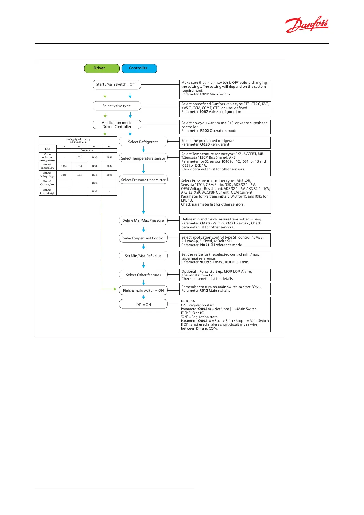
Make sure that main switch is OFF before changing
the settings. The setting will depend on the system
requirement.
Parameter: R012 Main Switch
Select predefined Danfoss valve type ETS, ETS C, KVS,
KVS C, CCM, CCMT, CTR, or user defined.
Parameter: I067 Valve configuration
Start : Main switch= Off
Select valve type
Application mode
Driver- Controller
Select how you want to use EKE: driver or superheat
controller.
Parameter: R102 Operation mode
Select Refrigerant
Select Temperature sensor
Select Pressure transmitter
Define Min/Max Pressure
Select Superheat Control
Set Min/Max Ref value
Select Other features
Finish: main switch = ON
DI1 = ON
Select the predefined refrigerant
.
Parameter: O030 Refrigerant
Select Temperature sensor type: EKS, ACCPBT, MB-
T,Sensata 112CP, Bus Shared, AKS
Parameter for S2 sensor: I040 for 1C, I081 for 1B and
I082 for EKE 1A.
Check parameter list for other sensors.
Select Pressure transmitter type –AKS 32R,
Sensata 112CP, OEM Ratio, NSK , AKS 32 1 - 5V,
OEM Voltage, Bus shared, AKS 32 1 - 6V, AKS 32 0 - 10V,
AKS 33, XSK, ACCPBP Current , OEM Current
Parameter for Pe transmitter: I043 for 1C and I085 for
EKE 1B.
Check parameter list for other sensors.
Define min and max Pressure transmitter in barg.
Parameter: O020 - Pe min., O021 Pe max., Check
parameter list for other sensors.
Select application control type SH control. 1: MSS,
2: LoadAp, 3: Fixed, 4: Delta SH.
Parameter: N021 SH reference mode.
Set the value for the selected control min./max.
superheat reference.
Parameter N009 SH max., N010 - SH min.
Optional – Force start up, MOP, LOP, Alarm,
Thermostat function.
Check parameter list for details.
Remember to turn on main switch to start ‘ON’ .
Parameter R012 Main switch.
IF EKE 1A
ON=Regulation start
Parameter O003 :0 = Not Used | 1 = Main Switch
IF EKE 1B or 1C
‘ON’ = Regulation start
Parameter O002: 0 = Bus –> Start / Stop 1 = Main Switch
If DI1 is not used, make a short circuit with a wire
between DI1 and COM.
Driver Controller
Analog signal type e.g
1-5 V/0-20 mA
EKE
1A 1B 1C 1D
Parameters
Driver
reference - 1091 1033 1091
Ext.ref.
Voltage,Low
1034 1034 1034 1034
Ext.ref.
Voltage,high
1035 1035 1035 1035
Ext.ref.
Current,Low
- - 1036 -
Ext.ref.
Current,high
- - 1037 -
default setting. Make sure that you activate other feature/function/ alarm as per the application requirement before