1.4.3 Removing the Upper Capacitor Bank
To remove the upper capacitor bank assembly, use the following procedure. Refer to Illustration 1.5.
NOTICE
The capacitor bank assembly weighs approximately 9 kg (20 lb).
1. Disconnect the IGBT wire harness from the following connectors on the gatedrive card:
1a MK100
1b MK101 (if RFI
lter
option is present)
1c MK102
1d MK103
1e MK104
1f MK105 (if brake option is present)
1g MK106
2. The capacitor bank connections to the DC busbars are recessed in the gap between the upper and lower capacitor banks.
A minimum extension of 150 mm (6 in) is required. Remove the 6 nuts (M5) connecting the upper capacitor bank to the
DC busbars.
3. Remove the 4 retaining nuts (M6), 1 from each corner of the upper capacitor bank.
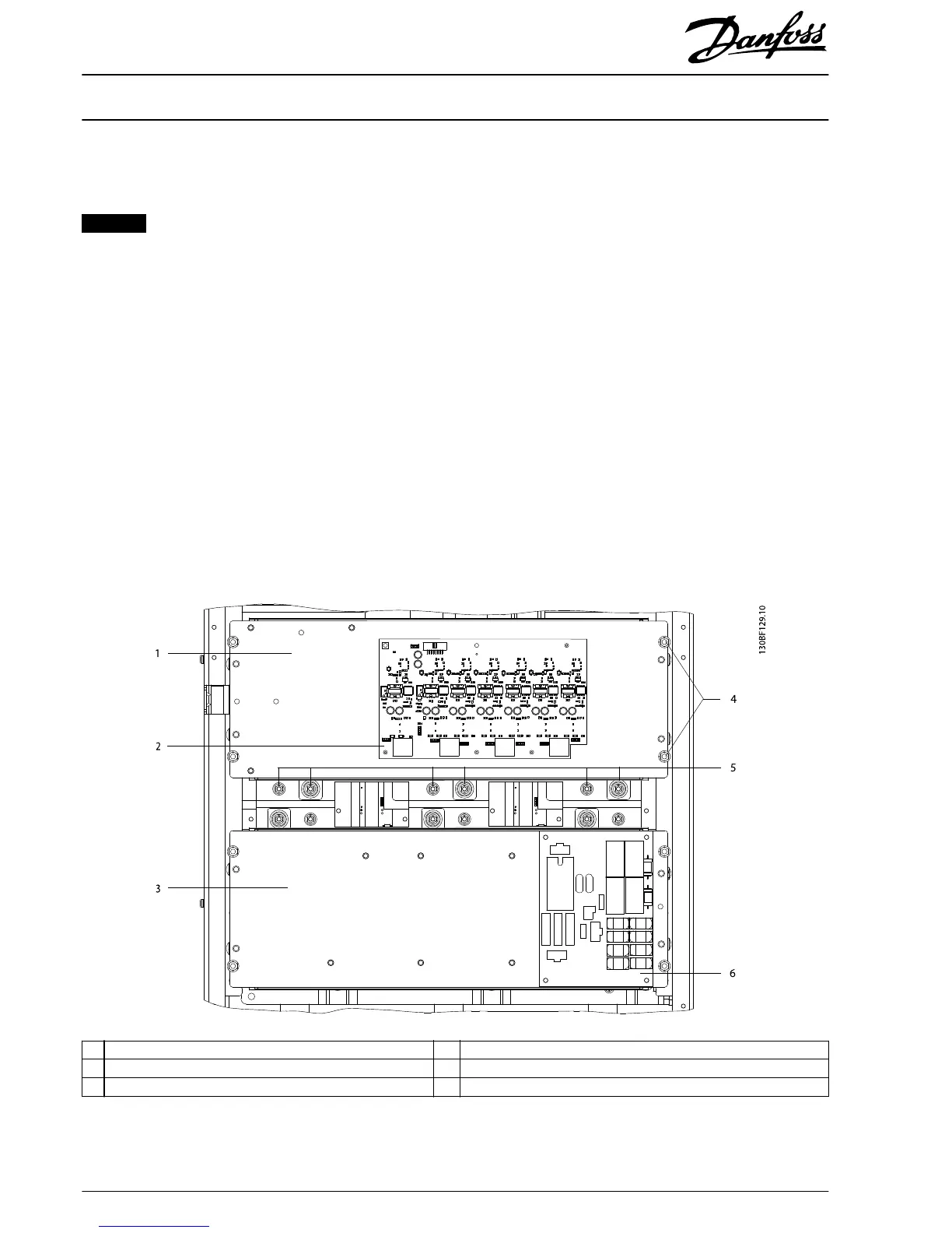
4. Lift the upper capacitor bank assembly from the unit. The gatedrive card can remain in place on the assembly.
1 Upper capacitor bank 4 Retaining nuts (M6)
2 Gatedrive card 5 Recessed connection nuts (M5)
3 Lower capacitor bank 6 Soft charge card
Illustration 1.5 Upper and Lower Capacitor Bank Assemblies
Installation Instructions
500 A Current Sensor Kit for
E1/E2 Enclosure Sizes
VLT
®
FC 102, FC 103, FC 202, FC 302
6
Danfoss A/S © 10/2016 All rights reserved. MI92Q102