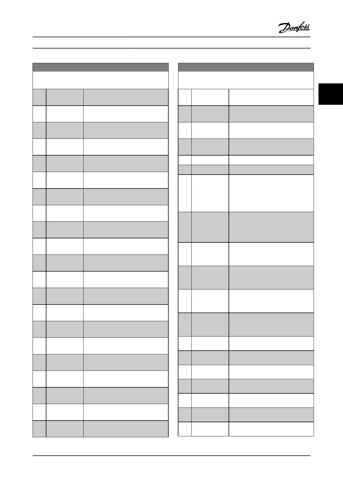
13-10 Comparator Operand
Array [6]
Option: Function:
[111] Logic rule 1 Logic rule 1 [111] The result of logic rule
1.
[112] Logic rule 2 Logic rule 2 [112] The result of logic rule
2.
[113] Logic rule 3 Logic rule 3 [113] The result of logic rule
3.
[114] Logic rule 4 Logic rule 4 [114] The result of logic rule
4.
[115] Logic rule 5 Logic rule 5 [115] The result of logic rule
5.
[120] SL Timeout 0 SL Timeout 0 [120] The result of SLC timer
0.
[121] SL Timeout 1 SL Timeout 1 [121] The result of SLC timer
1.
[122] SL Timeout 2 SL Timeout 2 [122] The result of SLC timer
2.
[123] SL Timeout 3 SL Timeout 3 [123] The result of SLC timer
3.
[124] SL Timeout 4 SL Timeout 4 [124] The result of SLC timer
4.
[125] SL Timeout 5 SL Timeout 5 [125] The result of SLC timer
5.
[126] SL Timeout 6 SL Timeout 6 [126] The result of SLC timer
6.
[127] SL Timeout 7 SL Timeout 7 [127] The result of SLC timer
7.
[130] Digital input
DI18
Digital input DI18 [130] Digital input 18.
High = True.
[131] Digital input
DI19
Digital input DI19 [131] Digital input 19.
High = True.
[132] Digital input
DI27
Digital input DI27 [132] Digital input 27.
High = True.
[133] Digital input
DI29
Digital input DI29 [133] Digital input 29.
High = True.
[134] Digital input
DI32
Digital input DI32 [134] Digital input 32.
High = True.
[135] Digital input
DI33
Digital input DI33 [135] Digital input 33.
High = True.
[150] SL digital output
A
SL digital output A [150] Use the result of
the SLC output A.
[151] SL digital output
B
SL digital output B [151] Use the result of
the SLC output B.
13-10 Comparator Operand
Array [6]
Option: Function:
[152] SL digital output
C
SL digital output C [152] Use the result of
the SLC output C.
[153] SL digital output
D
SL digital output D [153] Use the result of
the SLC output D.
[154] SL digital output
E
SL digital output E [154] Use the result of
the SLC output E.
[155] SL digital output
F
SL digital output F [155] Use the result of
the SLC output F.
[160] Relay 1 Relay 1 [160] Relay 1 is active
[161] Relay 2 Relay 2 [161] Relay 2 is active
[180] Local ref. active Local ref. active [180] High when
3-13 Reference Site = [2] Local or when
3-13 Reference Site is [0] Linked to hand
auto, at the same time as the LCP is in
hand on mode.
[181] Remote ref.
active
Remote ref. active [181] High when
3-13 Reference Site= [1] Remote or [0]
Linked to hand/auto, while the LCP is in
auto on mode.
[182] Start command Start command [182] High when there is
an active start command and no stop
command.
[183] Drive stopped Drive stopped [183] A stop command (Jog,
Stop, Qstop, Coast) is issued – and not
from the SLC itself.
[185] Drive in hand
mode
Drive in hand mode [185] High when the
adjustable frequency drive is in hand
mode.
[186] Drive in auto
mode
Drive in auto mode [186] High when the
adjustable frequency drive is in auto
mode.
[187] Start command
given
[190] Digital input x30
2
[191] Digital input x30
3
[192] Digital input x30
4
[193] Digital input x46
1
[194] Digital input x46
2
[195] Digital input x46
3
Parameter Descriptions FC 300 Programming Guide
MG.33.MA.22 - VLT
®
is a registered Danfoss trademark 3-111
3

 Loading...


