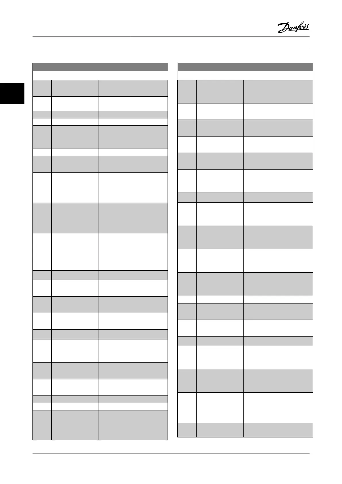
0-20 Display Line 1.1 Small
Option: Function:
[1618] Motor Thermal Thermal load on the motor,
calculated by the ETR function.
[1619] KTY sensor
temperature
[1620] Motor Angle
[1621] Torque [%] High Res.
[1622] Torque [%] Present motor load as a
percentage of the rated motor
torque.
[1625] Torque [Nm] High
[1630] DC Link Voltage Intermediate circuit voltage in the
adjustable frequency drive.
[1632] Brake Energy /s Present braking energy
transferred to an external brake
resistor.
Stated as an instantaneous value.
[1633] Brake Energy /2 min Braking energy transferred to an
external brake resistor. The mean
power is calculated continuously
for the most recent 120 seconds.
[1634] Heatsink Temp. Present heatsink temperature of
the adjustable frequency drive.
The cut-out limit is 203°±9°F [95°
±5°C]; cutting back in occurs at
158°F ±9°F [70°C ± 5°C].
[1635] Inverter Thermal Percentage load of the inverters.
[1636] Inv. Nom. Current Nominal current of the adjustable
frequency drive.
[1637] Inv. Max. Current Maximum current of the
adjustable frequency drive.
[1638] SL Controller State State of the event executed by
the control.
[1639] Control Card Temp. Temperature of the control card.
[1650] External Reference Sum of the external reference as a
percentage, i.e., the sum of
analog/pulse/bus.
[1651] Pulse Reference Frequency in Hz connected to the
digital inputs (18, 19 or 32, 33).
[1652] Feedback [Unit] Reference value from
programmed digital input(s).
[1653] Digi Pot Reference
[1657] Feedback [RPM]
[1660] Digital Input Signal states form the 6 digital
terminals (18, 19, 27, 29, 32 and
33). There are 16 bits in total, but
only six of them are used. Input
0-20 Display Line 1.1 Small
Option: Function:
18 corresponds to the leftmost of
the used bits. Signal low = 0;
Signal high = 1.
[1661] Terminal 53 Switch
Setting
Setting of input terminal 54.
Current = 0; Voltage = 1.
[1662] Analog Input 53 Actual value at input 53 either as
a reference or protection value.
[1663] Terminal 54 Switch
Setting
Setting of input terminal 54.
Current = 0; Voltage = 1.
[1664] Analog Input 54 Actual value at input 54 either as
reference or protection value.
[1665] Analog Output 42
[mA]
Actual value at output 42 in mA.
Use 6-50 Terminal 42 Output to
select the value to be shown.
[1666] Digital Output [bin] Binary value of all digital outputs.
[1667] Freq. Input #29 [Hz] Actual value of the frequency
applied at terminal 29 as an
impulse input.
[1668] Freq. Input #33 [Hz] Actual value of the frequency
applied at terminal 33 as an
impulse input.
[1669] Pulse Output #27 [Hz] Actual value of impulses applied
to terminal 27 in digital output
mode.
[1670] Pulse Output #29 [Hz] Actual value of impulses applied
to terminal 29 in digital output
mode.
[1671] Relay Output [bin]
[1672] Counter A Application dependent (e.g., SLC
Control)
[1673] Counter B Application dependent (e.g., SLC
Control)
[1674] Prec. Stop Counter Display the actual counter value.
[1675] Analog In X30/11 Actual value at input X30/11
either as reference or protection
value.
[1676] Analog In X30/12 Actual value at input X30/12
either as reference or protection
value.
[1677] Analog Out X30/8
[mA]
Actual value at output X30/8 in
mA. Use 6-60 Terminal X30/8
Output to select the value to be
shown.
[1678] Analog Out X45/1
[mA]
Parameter Descriptions FC 300 Programming Guide
3-6 MG.33.MA.22 - VLT
®
is a registered Danfoss trademark
3

 Loading...


