3-17 Reference Resource 3
Option: Function:
Select the reference input to be used
for the third reference signal.
3-15 Reference Resource 1,
3-16 Reference Resource 2 and
3-17 Reference Resource 3 define up to
three different reference signals. The
sum of these reference signals
defines the actual reference.
[0] No function
[1] Analog input 53
[2] Analog input 54
[7] Frequency input 29
[8] Frequency input 33
[11]
*
Local bus reference
[20] Digital pot.meter
[21] Analog input X30-11
[22] Analog input X30-12
[29] Analog Input X48/2
3-18 Relative Scaling Reference Resource
Option: Function:
Select a variable value to be added to the
fixed value (defined in 3-14 Preset Relative
Reference). The sum of the fixed and variable
values (labeled Y in the figure below) is
multiplied by the actual reference (labeled X
in the figure below). The result is then added
to the actual reference (X+X*Y/100) to give
the resulting actual reference.
This parameter cannot be adjusted while the
motor is running.
[0]
*
No function
[1] Analog input
53
[2] Analog input
54
[7] Frequency
input 29
[8] Frequency
input 33
[11] Local bus
reference
[20] Digital
pot.meter
3-18 Relative Scaling Reference Resource
Option: Function:
[21] Analog input
X30-11
[22] Analog input
X30-12
[29] Analog Input
X48/2
3-19 Jog Speed [RPM]
Range: Function:
Application
dependent
*
[Application
dependant]
Enter a value for the jog speed
n
JOG
, which is a fixed output
speed. The adjustable frequency
drive runs at this speed when the
jog function is activated. The
maximum limit is defined in
4-13 Motor Speed High Limit
[RPM].
See also 3-80 Jog Ramp Time.
3.5.3 Ramps
3-4* Ramp 1
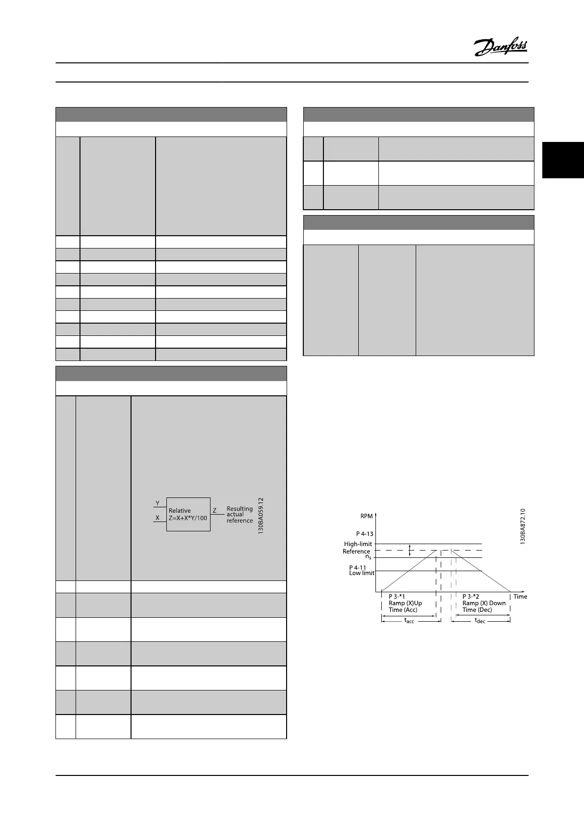
For each of four ramps (par. group 3-4*, 3-5*, 3-6* and 3-7*),
configure the ramp parameters: ramp type, ramping times
(duration of acceleration and deceleration) and level of jerk
compensation for S ramps.
Start by setting the linear ramping times corresponding to
the figures.
If S-ramps are selected, then set the level of non-linear jerk
compensation required. Set jerk compensation by defining
the proportion of ramp-up and ramp-down times where
acceleration and deceleration are variable (i.e., increasing or
decreasing). The S-ramp acceleration and deceleration
settings are defined as a percentage of the actual ramp time.
Parameter Descriptions FC 300 Programming Guide
MG.33.MA.22 - VLT
®
is a registered Danfoss trademark 3-35
3

 Loading...


