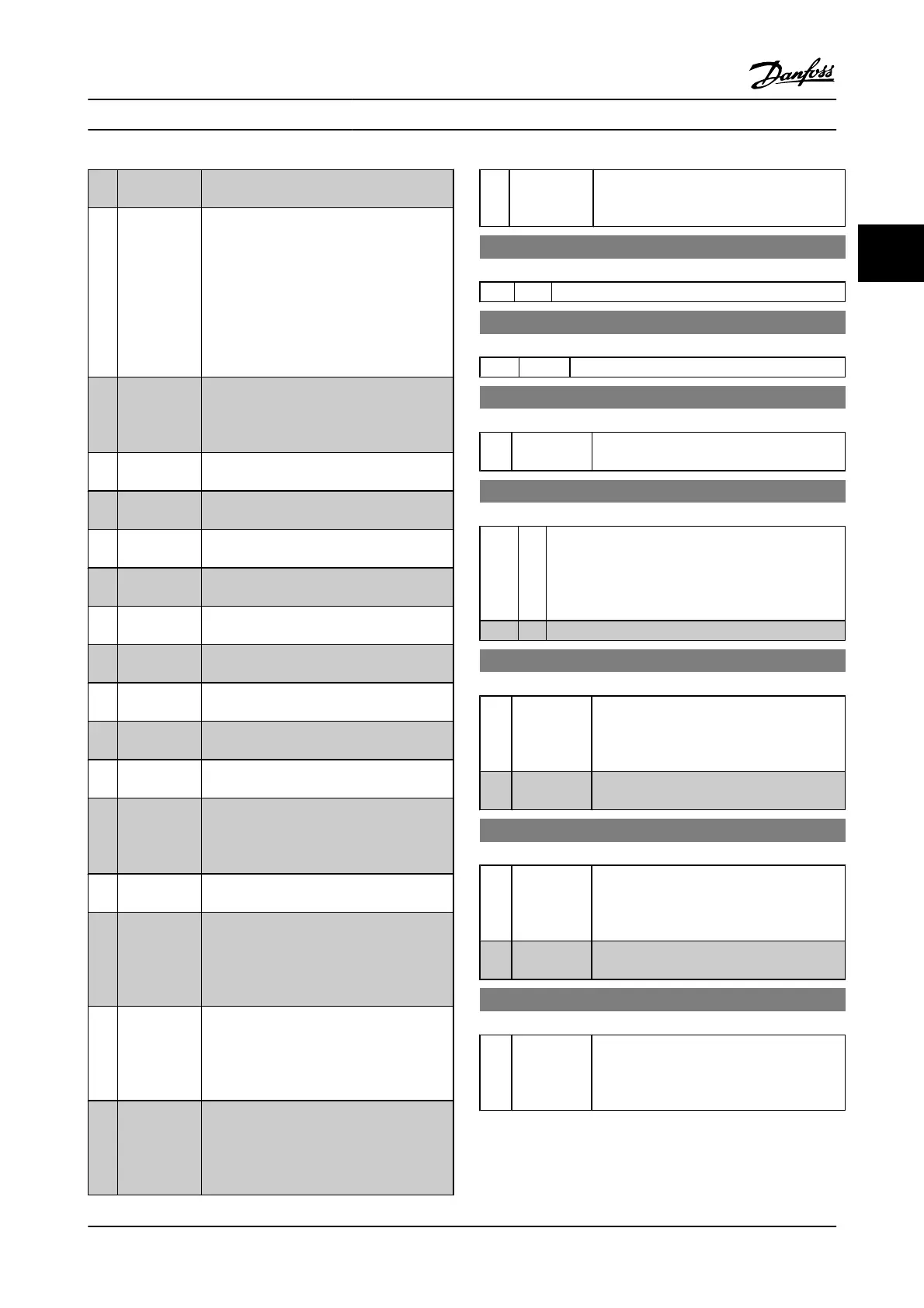
[36] Mains failure
inverse
Activates 14-10 Line Failure. Line failure inverse
is active in the logic .0. situation.
[40] Latched
Precise Start
A latched precise start only requires a pulse of
3ms on T18 or T19.
When using for 1-83 [1] or [2]:
When the reference is reached, the adjustable
frequency drive will internally enable the
precise stop signal. This means that the
adjustable frequency drive will do the precise
stop when the counter value of Par. 1-84 is
reached.
[41] Latched
Precise Stop
inverse
Sends a latched stop signal when the precise
stop function is activated in 1-83 Precise Stop
Function. The latched precise stop inverse
function is available for terminals 18 or 19.
[55] DigiPot
Increase
INCREASE signal to the digital potentiometer
function described in par. group 3-9*
[56] DigiPot
Decrease
DECREASE signal to the digital potentiometer
function described in par. group 3-9*
[57] DigiPot Clear Clears the digital potentiometer reference
described in par. group 3-9*
[60] Counter A (Terminal 29 or 33 only) Input for increment
counting in the SLC counter.
[61] Counter A (Terminal 29 or 33 only) Input for decrement
counting in the SLC counter.
[62] Reset Counter
A
Input for reset of counter A.
[63] Counter B (Terminal 29 or 33 only) Input for increment
counting in the SLC counter.
[64] Counter B (Terminal 29 or 33 only) Input for decrement
counting in the SLC counter.
[65] Reset Counter
B
Input for reset of counter B.
[70] Mech. Brake
Feedback
Brake feedback for hoisting applications: Set
1-01 Motor Control Principle to [3] flux w/ motor
feedback; set 1-72 Start Function to [6] Hoist
mech brake Ref.
[71] Mech. Brake
Feedback inv.
Inverted brake feedback for hoisting
applications
[72] PID error
inverse
When enabled, it inverts the resulting error
from the process PID controller. Available only
if "Configuration Mode" is set to "Surface
Winder," "Extended PID Speed OL" or
"Extended PID Speed CL."
[73] PID reset I-
part
When enabled, resets the I-part of the process
PID controller. Equivalent to 7-40 Process PID
I-part Reset. Available only if "Configuration
Mode" is set to "Surface Winder," "Extended
PID Speed OL" or "Extended PID Speed CL."
[74] PID enable When enabled, enables the extended process
PID controller. Equivalent to 7-50 Process PID
Extended PID. Available only if "Configuration
Mode" is set "Extended PID Speed OL" or
"Extended PID Speed CL."
[80] PTC Card 1 All digital inputs can be set to PTC card 1 [80].
However, only one digital input must be set to
this choice.
5-10 Terminal 18 Digital Input
Option: Function:
[8]
*
Start Functions are described under 5-1* Digital Inputs
5-11 Terminal 19 Digital Input
Option: Function:
[10]
*
Reverse Functions are described under 5-1* Digital Inputs
5-12 Terminal 27 Digital Input
Option: Function:
[2]
*
Coast inverse Functions are described under 5-1* Digital
Inputs
5-13 Terminal 29 Digital Input
Option: Function:
Select the function from the available digital input
range and the additional options [60], [61], [63] and
[64]. Counters are used in Smart Logic Control
functions. This parameter is available for the FC 302
only.
[14]
*
Jog Functions are described under 5-1* Digital Inputs
5-14 Terminal 32 Digital Input
Option: Function:
Select the function from the available digital
input range and the additional options [60],
[61], [63] and [64]. Counters are used in Smart
Logic Control functions.
[0]
*
No operation Functions are described under 5-1* Digital
Inputs
5-15 Terminal 33 Digital Input
Option: Function:
Select the function from the available digital
input range and the additional options [60],
[61], [63] and [64]. Counters are used in Smart
Logic Control functions.
[0]
*
No operation Functions are described under 5-1* Digital
Inputs
5-16 Terminal X30/2 Digital Input
Option: Function:
[0]
*
No operation This parameter is active when option module
MCB101 is installed in the adjustable
frequency drive. Functions are described
under 5-1* Digital Inputs
Parameter Descriptions FC 300 Programming Guide
MG.33.MA.22 - VLT
®
is a registered Danfoss trademark 3-51
3

 Loading...


