5-17 Terminal X30/3 Digital Input
Option: Function:
[0]
*
No operation This parameter is active when option module
MCB101 is installed in the adjustable
frequency drive. Functions are described
under 5-1* Digital Inputs
5-18 Terminal X30/4 Digital Input
Option: Function:
[0]
*
No operation This parameter is active when option module
MCB101 is installed in the adjustable
frequency drive. Functions are described
under 5-1* Digital Inputs
5-19 Terminal 37 Safe Stop
Option: Function:
[1]
*
Safe Stop
Alarm
Coasts adjustable frequency drive when safe
stop is activated. Manual reset from LCP, digital
input or serial communication bus.
[3] Safe Stop
Warning
Coasts adjustable frequency drive when safe
stop is activated (T-37 off). When the safe stop
circuit is reestablished, the adjustable
frequency drive will continue without manual
reset.
[4] PTC 1 Alarm Coasts adjustable frequency drive when safe
stop is activated. Manual reset from LCP, digital
input or serial communication bus. Choice 4 is
only available when the MCB 112 PTC
thermistor card is connected.
[5] PTC 1
Warning
Coasts adjustable frequency drive when safe
stop is activated (T-37 off). When the safe stop
circuit is reestablished, the adjustable
frequency drive will continue without manual
reset, unless a digital input set to PTC Card 1
[80] is still enabled. Choice 5 is only available
when the MCB 112 PTC thermistor card is
connected.
[6] PTC 1 &
Relay A
This choice is used when the PTC option is
gated together with a stop button through a
safety relay to T-37. Coasts adjustable
frequency drive when safe stop is activated.
Manual reset from LCP, digital input or serial
communication bus. Choice 6 is only available
when the MCB 112 PTC thermistor card is
connected.
[7] PTC 1 &
Relay W
This choice is used when the PTC option is
gated together with a stop button through a
safety relay to T-37. Coasts adjustable
frequency drive when safe stop is activated
(T-37 off). When the safe stop circuit is reestab-
lished, the adjustable frequency drive will
continue without manual reset, unless a digital
5-19 Terminal 37 Safe Stop
Option: Function:
input set to PTC Card 1 [80] is (still) enabled.
Choice 7 is only available when the MCB 112
PTC thermistor card is connected.
[8] PTC 1 &
Relay A/W
This choice makes it possible to use a
combination of alarm and warning. Choice 8 is
only available when the MCB 112 PTC
thermistor card is connected.
[9] PTC 1 &
Relay W/A
This choice makes it possible to use a
combination of alarm and warning. Choice 9 is
only available when the MCB 112 PTC
thermistor card is connected.
Choices 4–9 are only available when the MCB 112 PTC
thermistor card is connected.
NOTE!
When Auto Reset/ Warning is selected, the adjustable
frequency drive opens up for automatic restart.
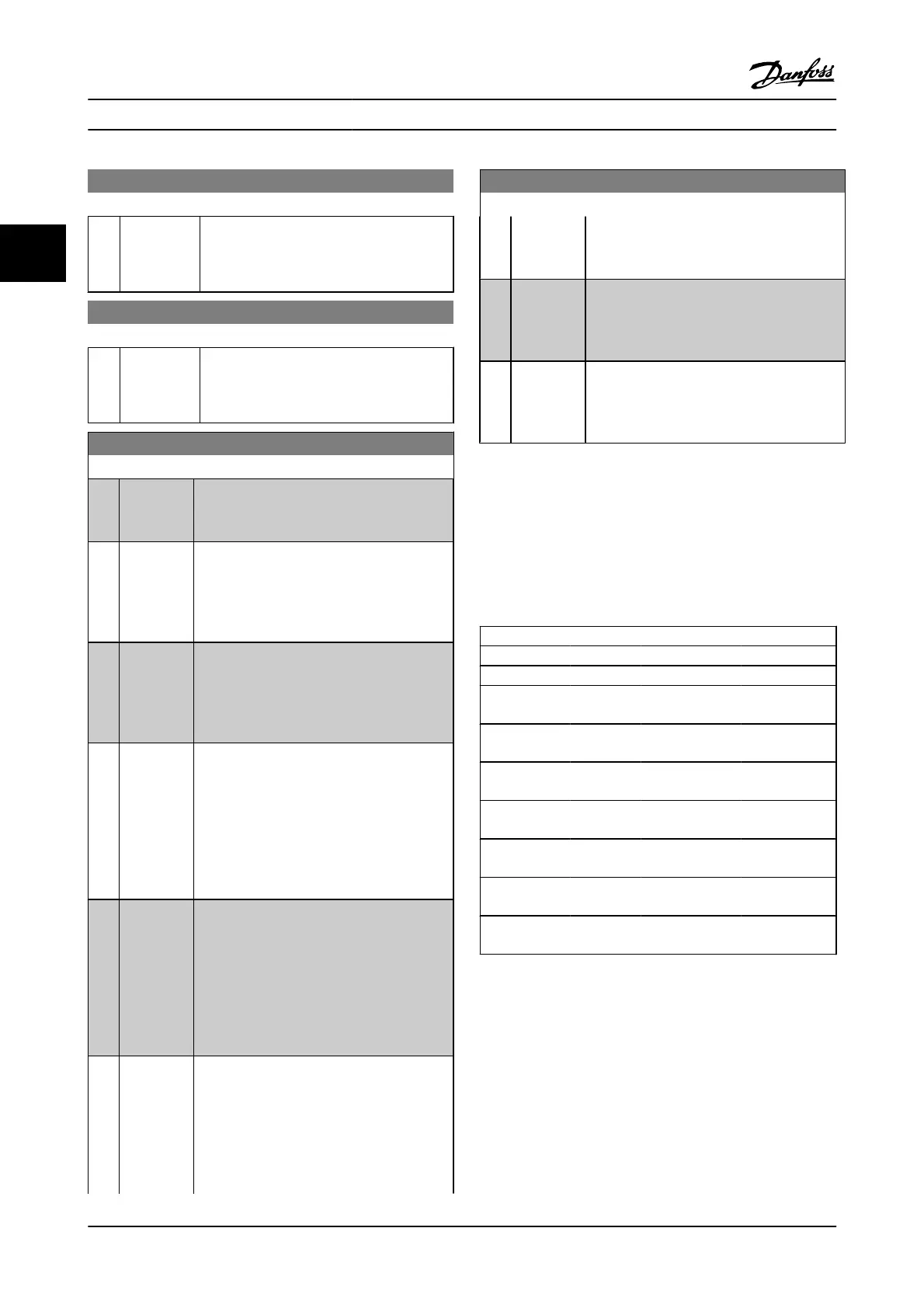
Overview of functions, alarms and warnings
Function No. PTC Relay
No Function [0] - -
Safe Stop Alarm [1]* - Safe Stop [A68]
Safe Stop
Warning
[3] - Safe Stop [W68]
PTC 1 Alarm [4] PTC 1 Safe Stop
[A71]
-
PTC 1 Warning [5] PTC 1 Safe Stop
[W71]
-
PTC 1 & Relay A [6] PTC 1 Safe Stop
[A71]
Safe Stop [A68]
PTC 1 & Relay W [7] PTC 1 Safe Stop
[W71]
Safe Stop [W68]
PTC 1 & Relay
A/W
[8] PTC 1 Safe Stop
[A71]
Safe Stop [W68]
PTC 1 & Relay
W/A
[9] PTC 1 Safe Stop
[W71]
Safe Stop [A68]
W means warning, and A means alarm. For further
information, see Alarms and Warnings in section Trouble-
shooting in the Design Guide or in the Instruction Manual.
A dangerous failure related to the safe stop will give alarm:
Dangerous Failure [A72].
Please refer to the section Description of Alarm Word, Warning
Word and extended Status Word in the chapter Trouble-
shooting.
Parameter Descriptions FC 300 Programming Guide
3-52 MG.33.MA.22 - VLT
®
is a registered Danfoss trademark
3

 Loading...


