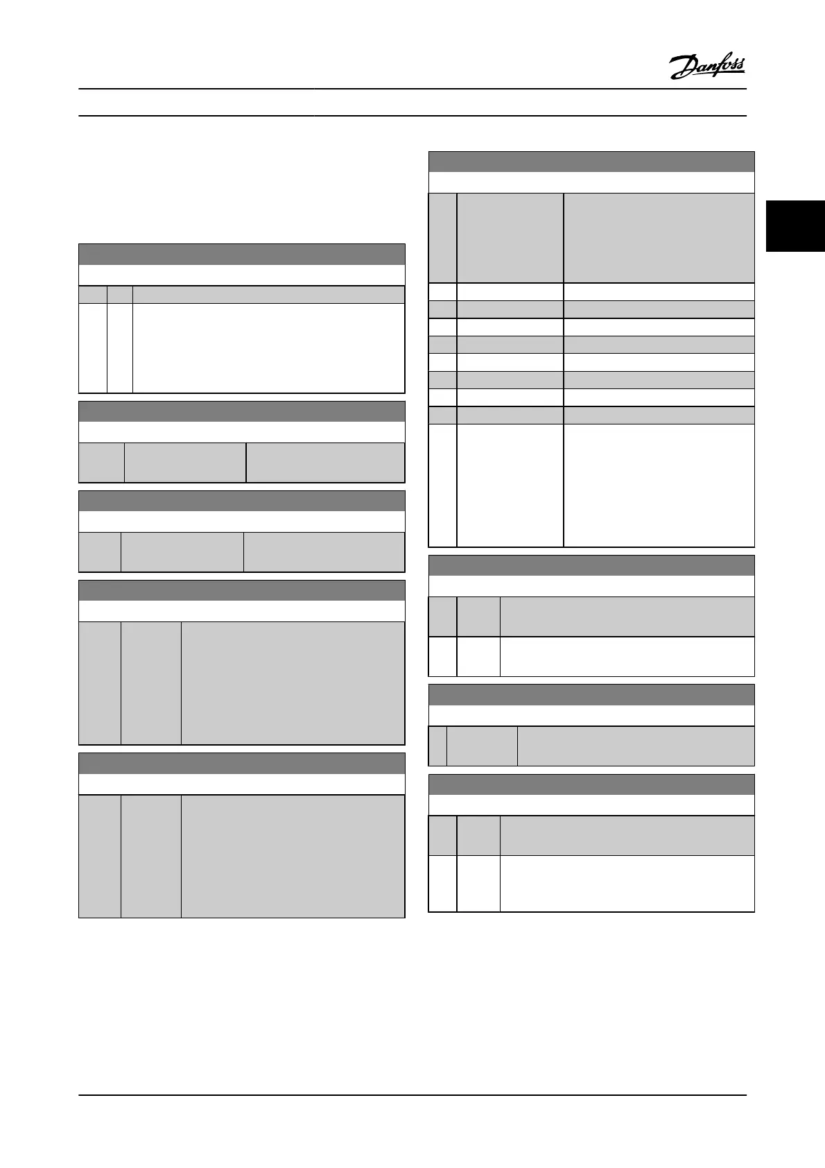
3.9.5 7-4* Adv. Process PID Ctrl.
Parameter group 7-4* is only used if par. 1-00 Configuration
Mode is set to [7] Extended PID speed CL or [8] Extended PID
Speed OL.
7-40 Process PID I-part Reset
Option: Function:
[0]
*
No
[1] Yes Select Yes [1] to reset the I-part of the process PID
controller. The selection will automatically revert to No
[0]. Resetting the I-part makes it possible to start from a
well-defined point after changing something in the
process, e.g., changing a textile roll.
7-41 Process PID Output Neg. Clamp
Range: Function:
-100 %
*
[Application
dependant]
Enter a negative limit for the
process PID controller output.
7-42 Process PID Output Pos. Clamp
Range: Function:
100 %
*
[Application
dependant]
Enter a positive limit for the
process PID controller output.
7-43 Process PID Gain Scale at Min. Ref.
Range: Function:
100 %
*
[0 - 100
%]
Enter a scaling percentage to apply to the
process PID output when operating at the
minimum reference. The scaling percentage
will be adjusted linearly between the scale at
min. ref. (7-43 Process PID Gain Scale at Min.
Ref.) and the scale at max. ref. (7-44 Process
PID Gain Scale at Max. Ref.).
7-44 Process PID Gain Scale at Max. Ref.
Range: Function:
100 %
*
[0 - 100
%]
Enter a scaling percentage to apply to the
process PID output when operating at the
maximum reference. The scaling percentage
will be adjusted linearly between the scale at
min. ref. (7-43 Process PID Gain Scale at Min.
Ref.) and the scale at max. ref. (7-44 Process
PID Gain Scale at Max. Ref.).
7-45 Process PID Feed Fwd Resource
Option: Function:
[0]
*
No function Select which drive input should be
used as the feed forward factor. The FF
factor is added directly to the output
of the PID controller. This increases
dynamic performance.
[1] Analog input 53
[2] Analog input 54
[7] Frequency input 29
[8] Frequency input 33
[11] Local bus reference
[20] Digital pot.meter
[21] Analog input X30-11
[22] Analog input X30-12
[32] Bus PCD Selects a bus reference configured by
Par. 8-02 Control Word Source. Change
PCD Write Configuration (8-42) for the
bus used in order to make the feed-
forward available in par. 7-48. Use
index 1 for feed-forward [748] (and
index 2 for reference [1682]).
7-46 Process PID Feed Fwd Normal/ Inv. Ctrl.
Option: Function:
[0]
*
Normal Select Normal [0] to set the feed forward factor to
treat the FF resource as a positive value.
[1] Inverse Select Inverse [1] to treat the FF resource as a
negative value.
7-48 PCD Feed Forward
Range: Function:
0
*
[0 - 65535 ] Readout parameter where the bus PCD feed
forward (par. 7-45 [32]) can be read.
7-49 Process PID Output Normal/ Inv. Ctrl.
Option: Function:
[0]
*
Normal Select Normal [0] to use the resulting output from
the process PID controller as is.
[1] Inverse Select Inverse [1] to invert the resulting output from
the process PID controller. This operation is
performed after the feed forward factor is applied.
Parameter Descriptions FC 300 Programming Guide
MG.33.MA.22 - VLT
®
is a registered Danfoss trademark 3-79
3

 Loading...


