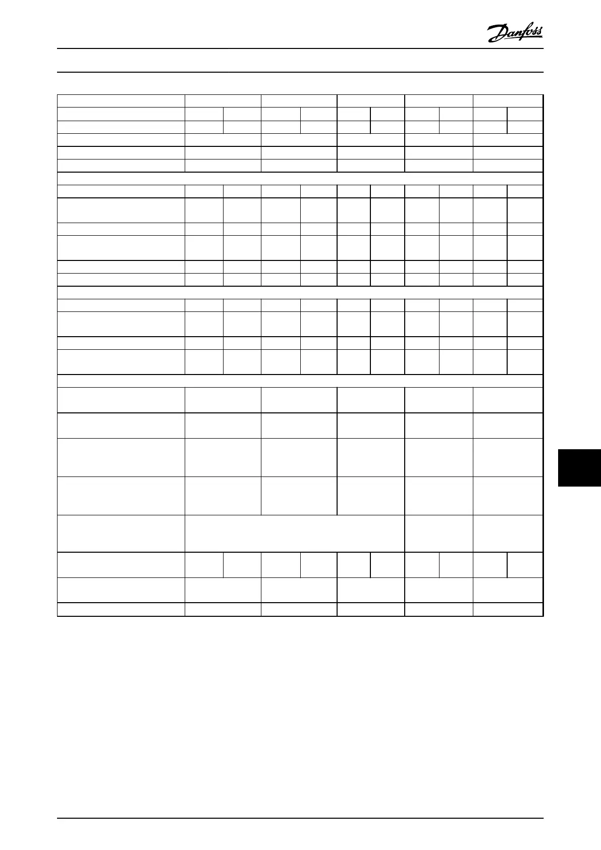
P30K P37K P45K P55K P75K
High/Normal Load
1)
HO NO HO NO HO NO HO NO HO NO
Typical Shaft output [kW] 30 37 37 45 45 55 55 75 75 90
Enclosure IP20 B4 C3 C3 C4 C4
Enclosure IP21 C1 C1 C1 C2 C2
Enclosure IP55, IP66 C1 C1 C1 C2 C2
Output current
Continuous (3x380-440 V) [A] 61 73 73 90 90 106 106 147 147 177
Intermittent (60 s overload)
(3x380-440 V) [A]
91.5 80.3 110 99 135 117 159 162 221 195
Continuous (3x441-500 V) [A] 52 65 65 80 80 105 105 130 130 160
Intermittent (60 s overload)
(3x441-500 V) [A]
78 71.5 97.5 88 120 116 158 143 195 176
Continuous kVA (400 V AC) [kVA] 42.3 50.6 50.6 62.4 62.4 73.4 73.4 102 102 123
Continuous kVA (460 V AC) [kVA] 51.8 63.7 83.7 104 128
Max. input current
Continuous (3x380-440 V) [A] 55 66 66 82 82 96 96 133 133 161
Intermittent (60 s overload)
(3x380-440 V) [A]
82.5 72.6 99 90.2 123 106 144 146 200 177
Continuous (3x441-500 V) [A] 47 59 59 73 73 95 95 118 118 145
Intermittent (60 s overload)
(3x441-500 V) [A]
70.5 64.9 88.5 80.3 110 105 143 130 177 160
Additional specifications
IP20 max. cable cross-section
5)
(mains and motor)
35 (2) 50 (1) 50 (1) 150 (300 MCM) 150 (300 MCM)
IP20 max. cable cross-section
5)
(brake and load sharing)
35 (2) 50 (1) 50 (1) 95 (4/0) 95 (4/0)
IP21, IP55, IP66 max. cable cross-
section
5)
(mains, motor) [mm
2
(AWG)]
2)
50 (1) 50 (1) 50 (1) 150 (300 MCM) 150 (300MCM)
IP21, IP55, IP66 max. cable cross-
section
5)
(brake, load sharing)
[mm
2
(AWG)]
2)
50 (1) 50 (1) 50 (1) 95 (3/0) 95 (3/0)
Max cable size with mains
disconnect [mm
2
(AWG)]
2)
50, 35, 35
(1, 2, 2)
95, 70, 70
(3/0, 2/0, 2/0)
185, 150, 120
(350 MCM, 300
MCM, 4/0)
Estimated power loss
at rated max. load [W]
4)
570 698 697 843 891 1083 1022 1384 1232 1474
Weight,
enclosure IP21, IP55, IP66 [kg]
45 45 45 65 65
Efficiency
4)
0.98 0.98 0.98 0.98 0.99
Table 10.6 Mains Supply 3x380-500 V AC (FC 302), 3x380-480 V AC (FC 301)
For fuse ratings, see 10.3.1 Fuses
1) High overload = 160% torque during 60 s. Normal overload = 110% torque during 60 s.
2) American Wire Gauge.
3) Measured using 5 m screened motor cables at rated load and rated frequency.
4) The typical power loss is at nominal load conditions and expected to be within
±
15% (tolerence relates to variety in voltage and
cable conditions).
Values are based on a typical motor efficiency (eff2/eff3 border line). Motors with lower efficiency will also add to the power loss in the
frequency converter and opposite.
If the switching frequency is increased compared to the default setting, the power losses may rise significantly.
Specifications
VLT
®
AutomationDrive Operating
Instructions
MG33AM02 - VLT
®
is a registered Danfoss trademark 69
10
10