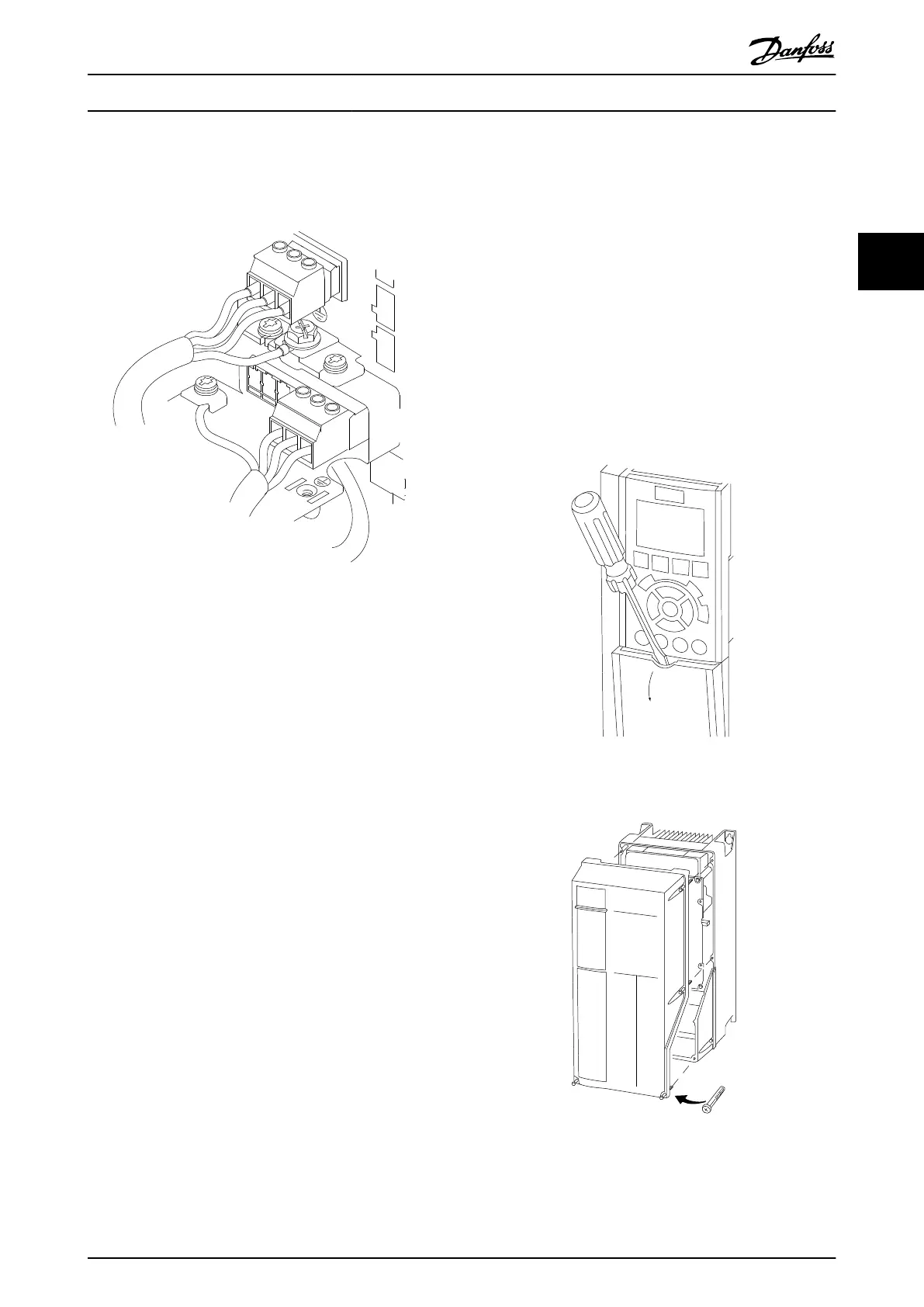
Illustration 2.8 represents mains input, motor, and earth
grounding for basic frequency converters. Actual configu-
rations vary with unit types and optional equipment.
95
130BB920.10
+DC
BR-
B
M A I N S
L1 L2 L3
91 92 93
RELAY 1 RELAY 2
99
- LC -
U V W
MOTOR
99
Illustration 2.8 Example of Motor, Mains and Earth Wiring
2.4.4
AC Mains Connection
•
Size wiring based upon the input current of the
frequency converter. For maximum wire sizes see
10.1 Power-dependent Specifications.
•
Comply with local and national electrical codes
for cable sizes.
•
Connect 3-phase AC input power wiring to
terminals L1, L2, and L3 (see Illustration 2.8).
•
Depending on the configuration of the
equipment, input power will be connected to the
mains input power or the input disconnect.
•
Ground the cable in accordance with grounding
instructions provided in 2.4.2 Earth (Grounding)
Requirements
•
All frequency converters may be used with an
isolated input source as well as with ground
reference power lines. When supplied from an
isolated mains source (IT mains or floating delta)
or TT/TN-S mains with a grounded leg (grounded
delta), set 14-50 RFI Filter to [0] Off. When off, the
internal RFI filter capacitors between the chassis
and the intermediate circuit are isolated to avoid
damage to the intermediate circuit and to reduce
earth capacity currents in accordance with IEC
61800-3.
2.4.5
Control Wiring
•
Isolate control wiring from high power
components in the frequency converter.
•
If the frequency converter is connected to a
thermistor, for PELV isolation, optional thermistor
control wiring must be reinforced/double
insulated. A 24 V DC supply voltage is
recommended.
2.4.5.1 Access
•
Remove access cover plate with a screw driver.
See Illustration 2.9.
•
Or remove front cover by loosening attaching
screws. See Illustration 2.10.
Illustration 2.9 Control Wiring Access for A2, A3, B3, B4, C3 and
C4 Enclosures
Illustration 2.10 Control Wiring Access for A4, A5, B1, B2, C1 and
C2 Enclosures
See Table 2.3 before tightening the covers.
Installation
VLT
®
AutomationDrive Operating
Instructions
MG33AM02 - VLT
®
is a registered Danfoss trademark 15
2
2