4.1.2 Setting LCP Display Values
The display area is activated when the frequency converter
receives power from mains voltage, a DC bus terminal, or
an external 24 V supply.
The information displayed on the LCP can be customized
for user application.
•
Each display readout has a parameter associated
with it.
•
Options are selected in main menu 0-2* LCP
Display
•
The frequency converter status at the bottom line
of the display is generated automatically and is
not selectable. See 7 Status Messages for
definitions and details.
1.1
2
3
1.3
1.2
130BP041.10
799 RPM
Auto Remote Ramping
1 (1)
36.4 kw7.83 A
0.000
53.2 %
Status
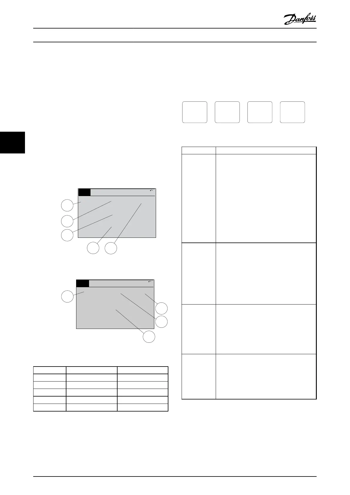
Illustration 4.2 Display Readouts
1.1
1.2
2
1.3
130BP062.10
207RPM
Auto Remote Running
1 (1)
24.4 kW5.25A
6.9
Hz
Status
Illustration 4.3 Display Readouts
Display Parameter number Default setting
1.1 0-20 Speed [RPM]
1.2 0-21 Motor Current
1.3 0-22 Power [kW]
2 0-23 Frequency
3 0-24 Reference [%]
Table 4.1 Legend to Illustration 4.2 and Illustration 4.3
4.1.3
Display Menu Keys
Menu keys are used for menu access for parameter set-up,
toggling through status display modes during normal
operation, and viewing fault log data.
130BP045.10
Status
Quick
Menu
Main
Menu
Alarm
Log
Illustration 4.4 Menu Keys
Key Function
Status Press to show operational information.
•
In Auto mode, press and hold to toggle
between status read-out displays
•
Press repeatedly to scroll through each
status display
•
Press and hold [Status] plus [
▲
] or [
▼
] to
adjust the display brightness
•
The symbol in the upper right corner of the
display shows the direction of motor
rotation and which set-up is active. This is
not programmable.
Quick Menu Allows access to programming parameters for
initial set up instructions and many detailed
application instructions.
•
Press to access Q2 Quick Setup for
sequenced instructions to program the basic
frequency controller set up
•
Follow the sequence of parameters as
presented for the function set-up
Main Menu Allows access to all programming parameters.
•
Press twice to access top-level index
•
Press once to return to the last location
accessed
•
Press and hold to enter a parameter
number for direct access to that parameter
Alarm Log Displays a list of current warnings, the last 5
alarms, and the maintenance log.
•
For details about the frequency converter
before it entered the alarm mode, select the
alarm number using the navigation keys
and press [OK].
Table 4.2 Legend to Illustration 4.4
User Interface
VLT
®
AutomationDrive Operating
Instructions
32 MG33AM02 - VLT
®
is a registered Danfoss trademark
44