4. Press the navigation keys to scroll to
0-03 Regional Settings and press [OK].
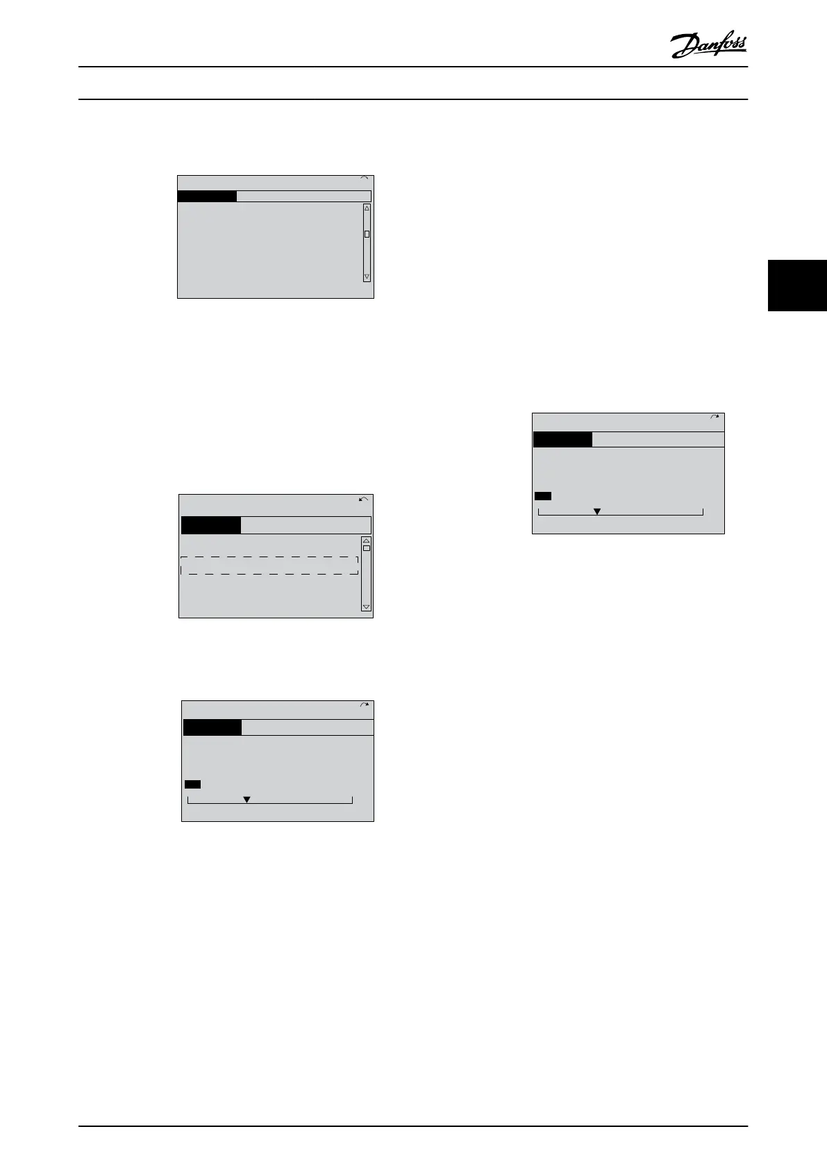
0-0
*
Basic Settings
0.0%
0-03 Regional Settings
[0] International
0.00A 1(1)
130BP088.10
Illustration 3.3 0-03 Regional Settings
5.
Press the navigation keys to select International
or North America as appropriate and press [OK].
(This changes the default settings for a number
of basic parameters. See for a complete list.)
6. Press [Quick Menu] on the LCP.
7. Press the navigation keys to scroll to parameter
group Q2 Quick Setup and press [OK].
130BB847.10
Q1 My Personal Menu
Q2 Quick Setup
Q5 Changes Made
Q6 Loggings
13.7% 13.0A 1(1)
Quick Menus
Illustration 3.4 Q2 Quick Setup
8. Select language and press [OK].
130BT772.10
Q2
0.0 Hz 0.00kW 1(1)
Motor Setup
1 - 21 Motor Power [kW]
4.0 kW
Illustration 3.5 Select Language
9. A jumper wire should be in place between
control terminals 12 and 27. If this is the case,
leave 5-12 Terminal 27 Digital Input at factory
default. Otherwise select No Operation. For
frequency converters with an optional bypass, no
jumper wire is required.
10.
3-02 Minimum Reference
11.
3-03 Maximum Reference
12.
3-41 Ramp 1 Ramp Up Time
13.
3-42 Ramp 1 Ramp Down Time
14.
3-13 Reference Site. Linked to Hand/Auto* Local
Remote.
3.4 Asynchronous Motor Setup
Enter the motor data in parameters 1-20/1-21 to 1-25. The
information can be found on the motor nameplate.
1.
1-20 Motor Power [kW] or 1-21 Motor
Power [HP]
1-22 Motor Voltage
1-23 Motor Frequency
1-24 Motor Current
1-25 Motor Nominal Speed
130BT772.10
Q2
0.0 Hz 0.00kW 1(1)
Motor Setup
1 - 21 Motor Power [kW]
4.0 kW
Illustration 3.6 Motor Setup
3.5
PM Motor Setup in VVC
plus
CAUTION
Do only use PM motor with fans and pumps.
Initial Programming Steps
1.
Activate PM motor operation 1-10 Motor
Construction, select [1) PM, non salient SPM
2.
Make sure to set 0-02 Motor Speed Unit to [0] RPM
Programming motor data.
After selecting PM motor in 1-10 Motor Construction, the
PM motor-related parameters in parameter groups 1-2*,
1-3* and 1-4* are active.
The information can be found on the motor nameplate
and in the motor data sheet.
Following parameters must be programmed in the listed
order
1.
1-24 Motor Current
2.
1-26 Motor Cont. Rated Torque
3.
1-25 Motor Nominal Speed
4.
1-39 Motor Poles
5.
1-30 Stator Resistance (Rs)
Enter line to common stator winding resistance
(Rs). If only line-line data are available, divide the
line-line value with 2 to achieve the line to
common (starpoint) value.
Start Up and Functional Tes...
VLT
®
AutomationDrive Operating
Instructions
MG33AM02 - VLT
®
is a registered Danfoss trademark 27
3 3