5.
6-11 Terminal 53 High Voltage. Set maximum
external voltage reference on Terminal 53 at 10 V
(this sets the maximum input signal at 10 V).
Q3-21
130BT765.10
6-11 Terminal 53 High
Voltage
10.00 V
14.7% 0.00A 1(1)
Analog Reference
Illustration 5.5 6-11 Terminal 53 High Voltage
6.
6-14 Terminal 53 Low Ref./Feedb. Value. Set
minimum speed reference on Terminal 53 at 6 Hz
(this tells the frequency converter that the
minimum voltage received on Terminal 53 (0 V)
equals 6 Hz output).
130BT773.11
Q3-21
14.7 % 0.00 A 1(1)
Analog Reference
6 - 14 Terminal 53 Low
Ref./Feedb. Value
000020.000
Illustration 5.6
6-14 Terminal 53 Low Ref./Feedb. Value
7.
6-15 Terminal 53 High Ref./Feedb. Value. Set
maximum speed reference on Terminal 53 at 60
Hz (this tells the frequency converter that the
maximum voltage received on Terminal 53 (10 V)
equals 60 Hz output).
130BT774.11
Q3-21
14.7 % 0.00 A 1(1)
Analog Reference
6 - 15 Terminal 53 High
Ref./Feedb. Value
50.000
Illustration 5.7 6-15 Terminal 53 High Ref./Feedb. Value
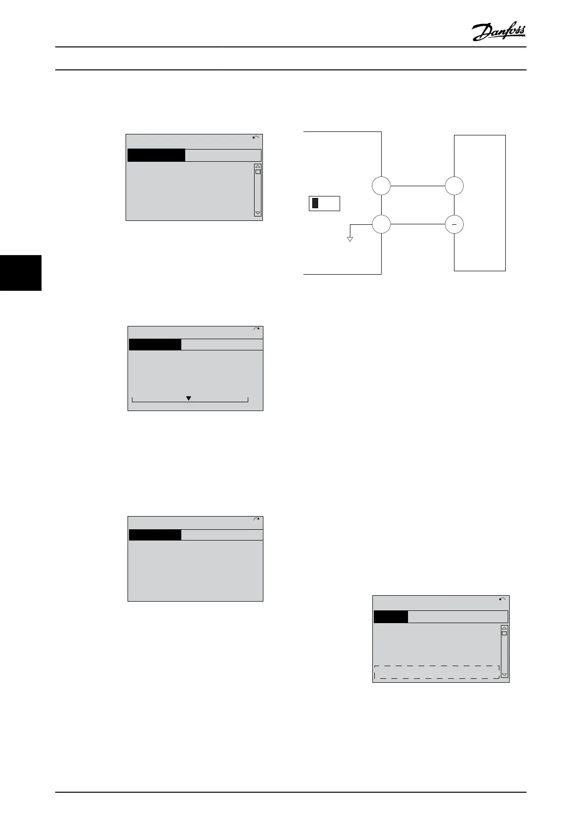
With an external device providing a 0-10 V control signal
connected to frequency converter terminal 53, the system
is now ready for operation.
NOTE
When the procedure is complete, the scroll bar is at the
bottom.
Illustration 5.8 shows the wiring connections used to
enable this set up.
53
55
6-1*
+
A53
U - I
130BB482.10
0-10V
Illustration 5.8 Wiring Example for External Device Providing
0-10 V Control Signal (frequency converter left, external device
right)
5.3 Control Terminal Programming
Examples
Control terminals can be programmed.
•
Each terminal has specified functions it is capable
of performing
•
Parameters associated with the terminal enable
the function
See Table 2.5 for control terminal parameter number and
default setting. (Default setting can change based on the
selection in 0-03 Regional Settings.)
The following example shows accessing Terminal 18 to see
the default setting.
1. Press [Main Menu] twice, scroll to parameter
group 5-** Digital In/Out Parameter Data Set and
press [OK].
130BT768.10
2-** Brakes
3-** Reference / Ramps
4-** Limits / Warnings
5-** Digital In/Out
14.6% 0.00A 1(1)
Main Menu
Illustration 5.9
6-15 Terminal 53 High Ref./Feedb. Value
About Frequency Converter P...
VLT
®
AutomationDrive Operating
Instructions
36 MG33AM02 - VLT
®
is a registered Danfoss trademark
5
5