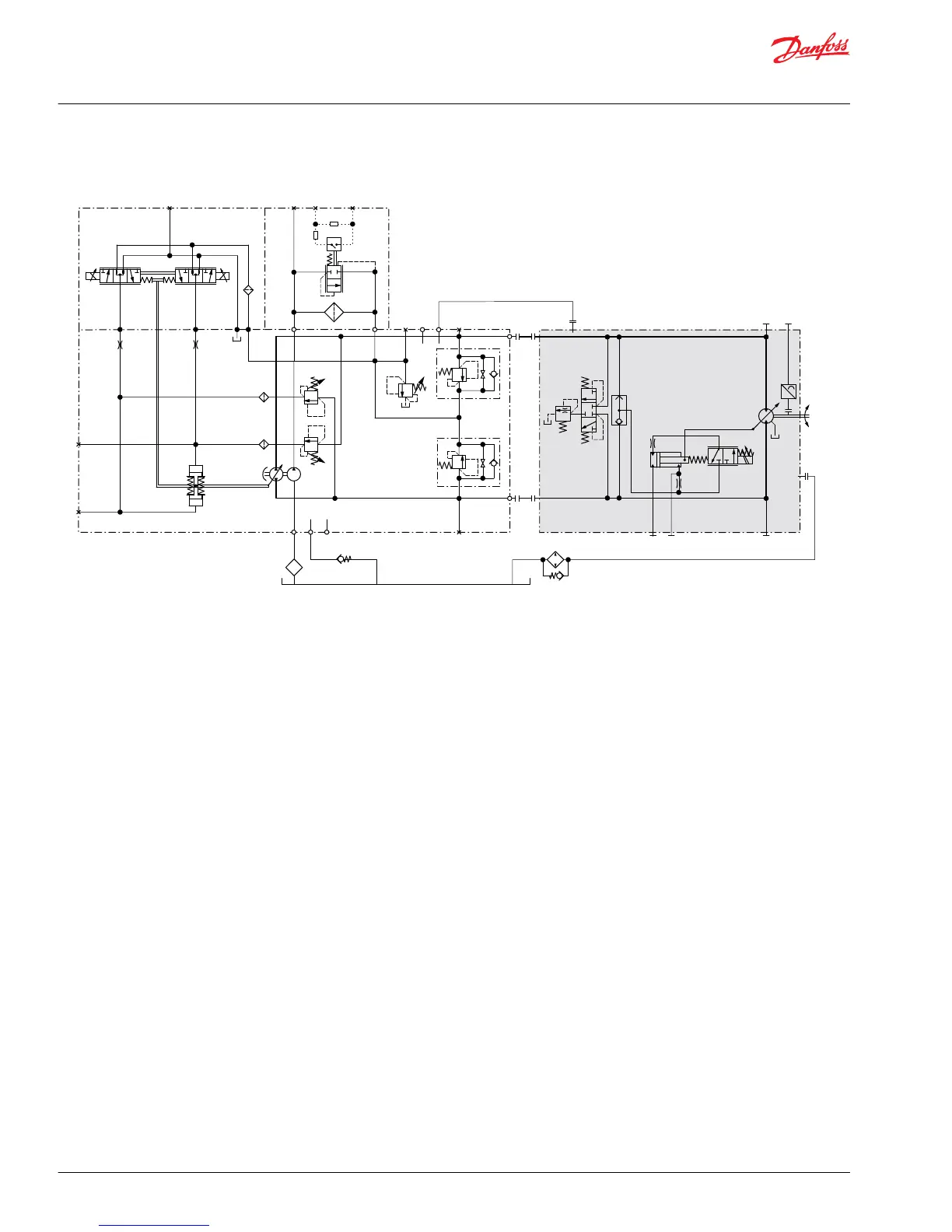
The schematic above shows the function of a hydrostatic transmission using an H1 axial variable
displacement pump with electric proportional displacement control (EDC) and an H1 bent axis variable
displacement motor with electric proportional control (L*) and integrated loop flushing device.
Service Manual
H1 Pumps 069/078, 089/100, 115/130, 147/165, 210/250
Introduction
10 |
©
Danfoss | May 2018 520L0848 | AX00000087en-US0308