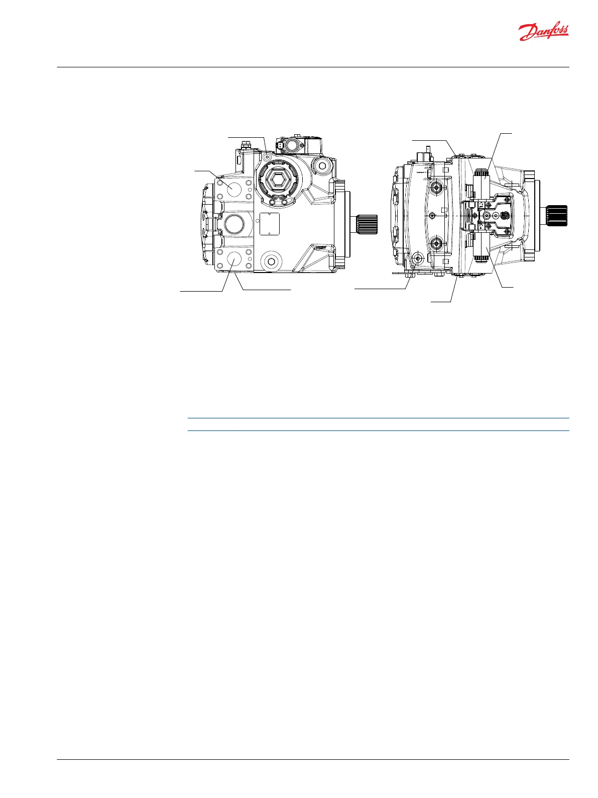
System Pressure Gauge Ports
System
Port B
Servo pressure
port M4
System Port A
Servo pressure
port M4
Servo pressure
port M5
Solenoid C1
Solenoid C2
Gauge port MB
system pressure
Gauge port MA
system pressure
P106 489E
For more information see H1P Ports Information on page 26.
1. Attach a 50 bar [1000 psi] gauge to each servo pressure port M4 and M5.
2. Attach a 600 bar [10 000 psi] gauge to each system pressure port (MA and MB).
3. Remove servo cylinder locking screws (E350) and plates (E300) from both sides of the pump.
4. Disconnect the control solenoids from the vehicle wiring harness.
5. If using a PWM signal to set mechanical neutral, connect the control solenoids C1 and C2 to the signal
source.
Ensure the source supplies no current to the solenoids until required in the following procedure.
Service Manual
H1P 069—H1P 280 Axial Piston Single Pumps
Adjustments
©
Danfoss | January 2021 AX152886482551en-000601 | 41
 Loading...


