Application guidelines
12 FRCC.PC.002.A4.22
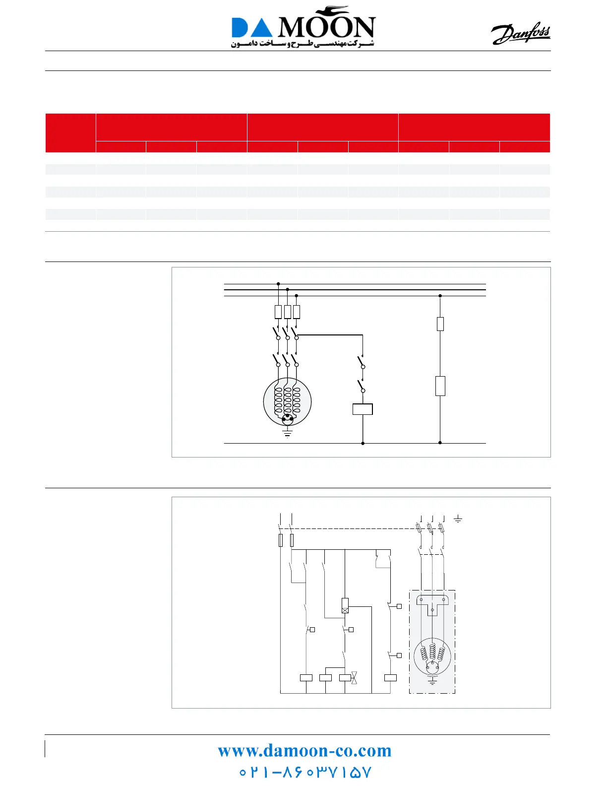
Electrical connections and wiring
FU Fuses
MS Main switch
C1 Compressor contactor
TH Thermostat
EC External controls
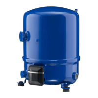
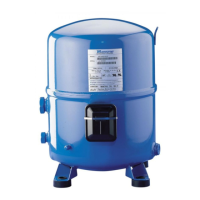
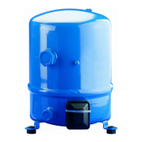
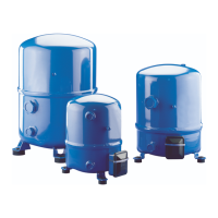
COMP Compressor
PTC Crankcase heater
IOL Internal overload line break
Three phase electrical
characteristics
Three phase motor
protection and suggested
wiring diagram
Wiring diagram with
pump-down cycle
Control device TH
Optional short cycle timer (3 min) 180 s
Control relay KA
Liquid Solenoid valve LLSV
Compressor contactor KM
Safety lock out relay KS
Pump-down control & L.P. switch BP
H.P. switch HP
Fused disconnect Q1
Fuses F1
Compressor motor M
Discharge gas thermostat DGT
M
DGT
HP
180 s
TH
LP
CONTROL CIRCUIT
F1F1
KM
KM
KM
KA KA
A1
A2
A3
KA
KA
KS
KS
KS
L1 L3 L2
Q1
T1
T3
T2
LLSV KS
PTC
FU
FU
C1
EC
TH
N
L1
L2
L3
C1
MS
IOL
Comp.
Compressor
model
LRA
(Locked Rotor Amp) A
MCC
(Maximum Continuous Current) A
Winding resistance (Ω)
(between phases +/- 7% at 77°F)
3 4 9 3 4 9 3 4 9
NTZ048 32 16 22 10.1 4.8 5 2.80 11.55 13.10
NTZ068 48.5 25 29 14.8 8.4 8.5 1.58 7.11 9.70
NTZ096 72 32 20.4 10.1 1.20 5.03
NTZ108 72 45 57 21.4 12.1 11 1.20 4.00 2.54
NTZ136 97.2 51 64 29 14.3 15 0.98 3.80 2.54
NTZ215 147.7 74 110 42.3 22.3 23 0.57 2.23 1.26
NTZ271 198 96 150 56.5 27.0 30 0.41 1.61 0.84
 Loading...