Application guidelines
17FRCC.PC.002.A4.22
System design recommendations
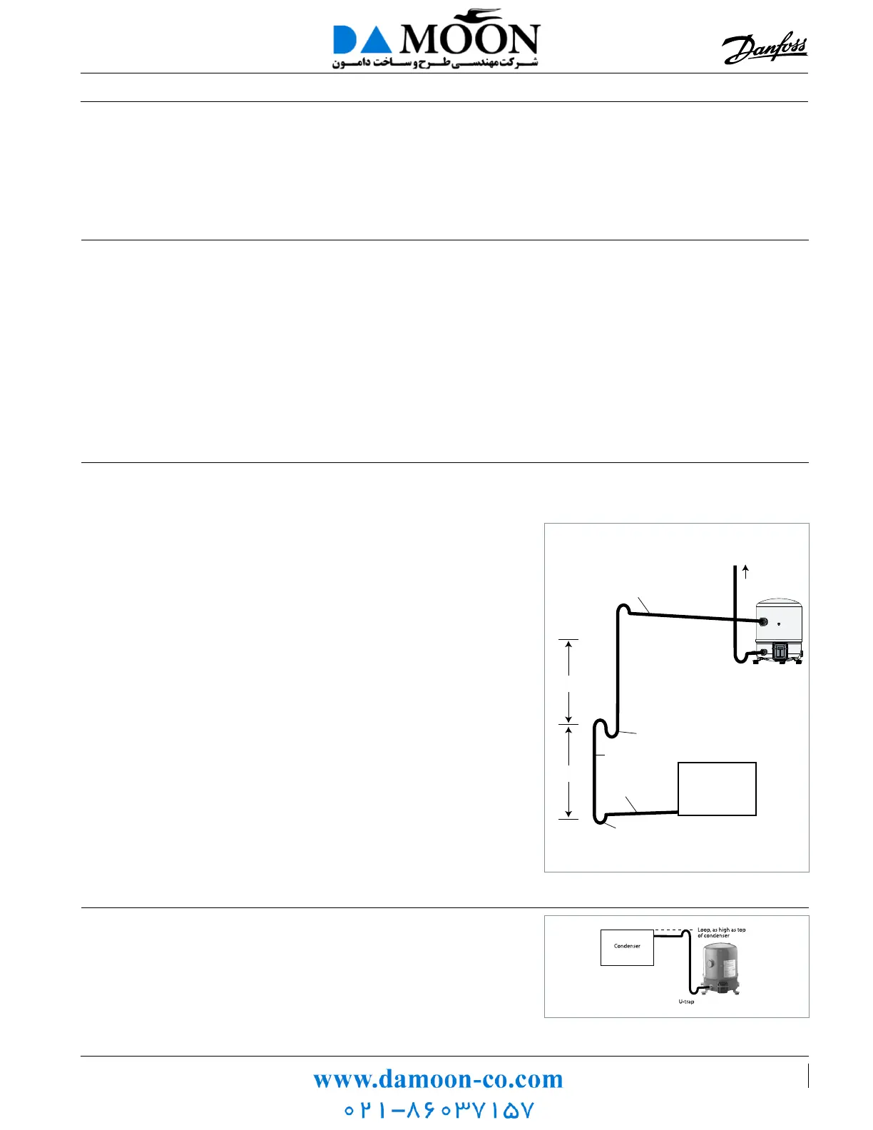
Suction line
Piping design
Horizontal suction line sections shall have a slope
of 0.5% in the direction of refrigerant ow (5/8”
per 10 ft of pipe).The cross-section of horizontal
suction lines shall be such that the resulting gas
velocity is at least 13 ft/s. In vertical risers, a gas
velocity of 26 to 40 ft/s is required to ensure
proper oil return.
A U-trap is required at the foot of each vertical
riser. If the riser is higher than 13 ft, additional
U-traps are required for each additional 13ft.
The length of each U-trap must be as short as
possible to avoid the accumulation of excessive
quantities of oil (see gure below).
Gas velocities higher than 40 ft/s will not con-
tribute to signicantly better oil return. However
they will cause higher noise levels and result in
higher suction line pressure drops which will
have a negative eect on the system capacity.
Note that the suction rotolock valves, which
can be ordered from Danfoss as accessories, are
designed for average pipe sizes, selected for
systems running at nominal conditions. The pipe
sizes selected for specic systems may dier from
these average sizes.
The suction line must always be insulated to limit
suction gas superheat.
Oil in a refrigeration circuit is required to lubricate
moving parts in the compressor. During nor-
mal system operation small oil quantities will
continuously leave the compressor, with the
discharge gas. Therefore, the system piping shall
be designed in a way which allows a good oil
circulation, avoiding oil being trapped in the
system and ensuring a constant oil return to the
compressor. As long as the amount of oil circulat-
ing through the system is small it will contribute
to good system operation and improved heat
transfer eciency.
Lubricant getting trapped in the evaporator or
suction lines will aect system performance and
will ultimately lead to compressor lubrication
failures. Where a poor oil return situation exists,
adding lubricant will not help safeguard the com-
pressor. Only a correct piping design can ensure
adequate oil circulation maintaining safe oil level
in the compressor.
Maneurop® NTZ compressors have been de-
signed and qualied for stationary equipment
using standard alternating power supply. Danfoss
does not warrant the compressors for use on
mobile applications such as trucks, railways,
subways, ships etc.
These selection and application guidelines con-
cern single compressors only. For guidelines on
manifolding Maneurop® NTZ compressors, please
refer to literature called "Parallel Application
Guidelines".
Discharge line When the condenser is mounted above the
compressor, a loop above the condenser and a
U-trap close to the compressor are required to
prevent liquid draining from the condenser into
the discharge line during standstill.
0.5 % slope,
13 ft/s or more
0.5 % slope,
13 ft/s or more
To condenser
max. 13 ft
max. 13 ft
26 to 40 ft/s
U-trap, as short as possible
U-trap, as short as possible
U-trap
Evaporator
 Loading...