11
TMC Software
Overview
Operation
Definitions
Cabin Station
One TMC controller on the machine is designated as the cabin station. Machine inputs and outputs
(motor speed PPU, configuration, charge and discharge outputs, and
CAN bus) are connected to the cabin station controller’s connector pins.
Remote Station
Up to four remote stations can be installed on a vehicle. Remote stations are only connected to the
vehicle’s CAN bus and power—other connector input and output pins are not used.
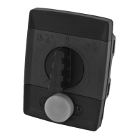
LED Indicator
The TMC station status is provided to the operator by a dual color (amber/red) LED located to the
right of the yellow control button, see Unit Dimensions, page 6.
TMC software controls the operation of a transit mixer drum by reading inputs from the TMC
controller’s input pins, CAN bus, operator control dial and operator switch, and by providing control
outputs to the TMC controller’s output pins and CAN bus.
The TMC software uses drum motor and engine speed to provide control inputs to the proportional
integral derivative controller (PID controller) algorithm controlling drum motor speed. Engine speed
is also controlled by the software when the vehicle is in work mode.
The TMC controller has two digital input configuration pins, allowing up to 4 sets of parameters to be
stored in the memory of the controller. This feature allows OEMs the flexibility to use the TMC
controller with hydraulic systems from different suppliers.
TMC Station Status
Indication Status
LED not illuminated Another TMC station is active
Blinking amber LED No TMC station is active
Solid amber LED The TMC station is active
Blinking red LED Error condition. See Error Codes, page 12, for error blink code information.
Active Station
The active TMC is the controller receiving operator inputs and sending outputs to the vehicle.
Activate Function
Each time a vehicle’s engine is started, one TMC station must be activated. To activate a specific TMC,
that TMC’s rotary dial must be in the neutral (center) position and the yellow TMC control button must
be pressed for two seconds.
Overtaking Control Function
This function transfers operator control from one TMC on the machine to another if more than one
TMC is installed on a vehicle. To make a specific TMC active, that TMC’s rotary dial must be in the
neutral (center) position and the yellow TMC control button must be pressed for two seconds.