Caution
Contamination can damage internal components and void the manufacturer’s warranty. Take
precautions to ensure system cleanliness when removing and reinstalling system lines
1. With the prime mover off, thoroughly clean all dirt and grime from the outside of the pump.
2. If removing the pump, tag each hydraulic line connected to the pump. If hydraulic lines are
disconnected, plug each open port, to ensure that dirt and contamination do not get into the pump.
3. Ensure the surrounding areas are clean and free of contaminants such as dirt and grime.
4. Inspect the system for contamination.
5. Look at the hydraulic fluid for signs of system contamination, oil discoloration, foam in the oil, sludge,
or small metal particles.
6. Drain and flush the hydraulic system and replace all filters.
7. Before re-installing the pump, perform a leakage test per Sauer-Danfoss leakage test HPP 112.
Warranty
Performing installation, maintenance, and minor repairs according to the procedures in this manual will
not affect your warranty. Major repairs, requiring the removal of a unit’s rear cover or front flange, voids
the warranty unless done by a Danfoss Global Service Partner.
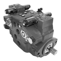
Pump adjustment
This section offers instruction on inspection and adjustment of pump components. Read through the
entire topic before beginning a service activity. Refer to Pressure measurements on page 13, for location of
gauge ports and suggested gauge size.
Charge pressure relief valve
The following procedure explains how to check and adjust the charge pressure relief valve.
1. Shut down prime mover.
2. Install a 50 bar [1000 psi] pressure gauge in charge pressure gauge port M3. Install a 10 bar [100 psi]
gauge in one of the case pressure ports L1 or L Operate the system with the pump in neutral (zero
displacement) to measure charge pressure.
Measure charge pressure at 1775 RPM. Charge pressure is found by subtracting case pressure from
the pressure measured at the charge pressure gage port M3.
3. To adjust charge pressure, shut down prime mover.
4. Using a 1 inch hex wrench, remove charge pressure relief plug (102). Add or remove shims (101) in
relief valve. Adding shims (101) increases charge pressure, while removing shims decreases charge
pressure. Refer to pump model code for the unit’s proper charge pressure setting.
5. Lubricate and install new O-ring O-ring (103).
6. Using a 1 inch hex wrench, reinstall plug (102). Torque to 108 Nm [80 ft•lb].
7. Operate pump in neutral to verify proper operation.
Service Manual
Series 40 M46 Tandem Variable Pumps
Adjustments
©
Danfoss | September 2017 11029852 | AX00000030en-US0202 | 19

 Loading...