Measured data
•
System pressure at MA or MC
•
System pressure at MB or MC
•
Pressure differential between MA and MB or MC and MD (optional)
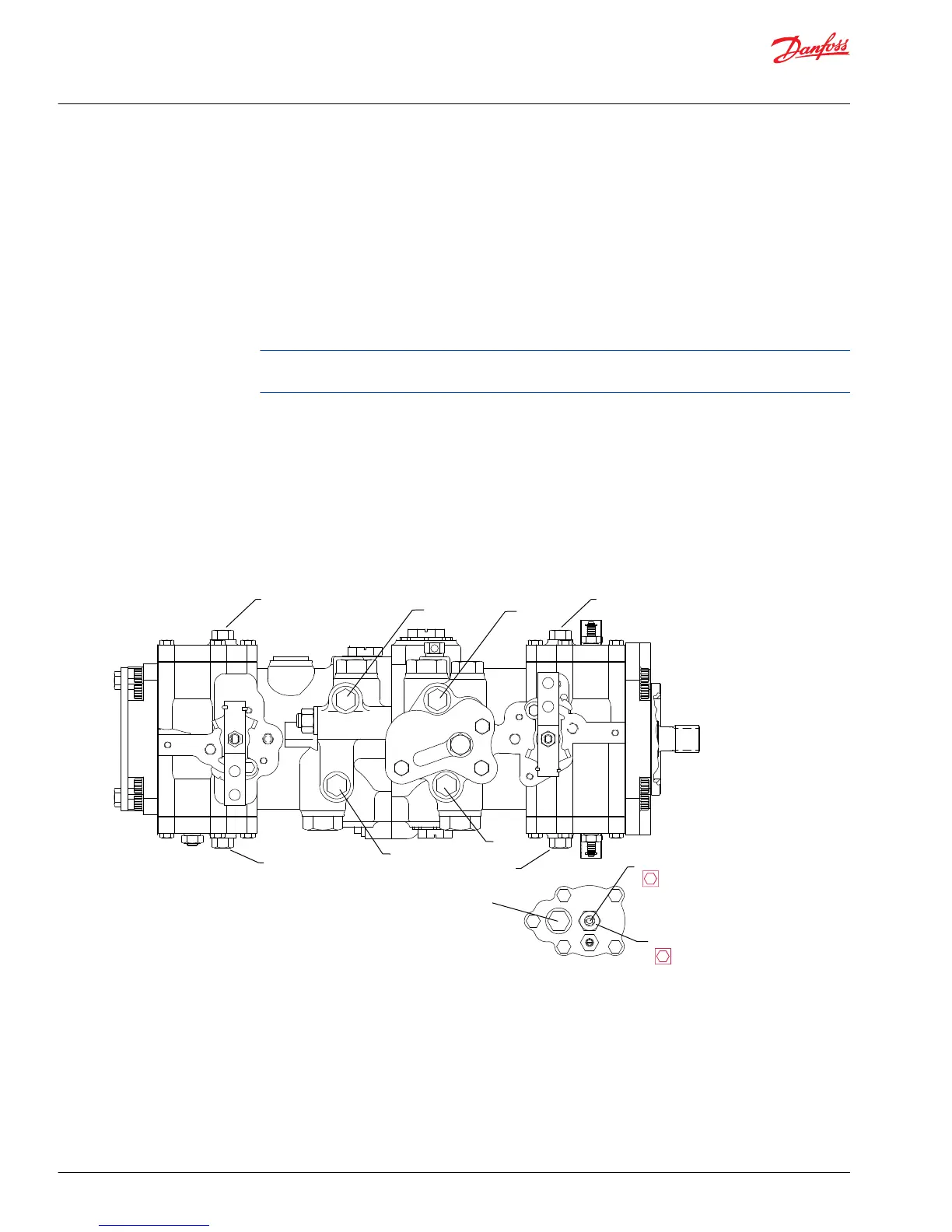
Pump Setup
1. Attach 600 bar [10,000 psi] gauge to system pressure gage ports MA and MB or MC and MD
2. Using a hydraulic line and fittings, connect servo pressure ports (M4 and M5).
Connecting servo ports M4 and M5 removes the effects of any control pressure on the servo piston by
creating zero pressure differential between the two sides of the servo.
3. Using a 1/4 hex wrench and a 9/16 hex wrench, loosen servo lock nut (2115).
4. Using a 1/4 hex wrench, turn neutral adjustment screw (908) until one system pressure gage begins
to show an increase in pressure. Turn the neutral adjustment screw (908) in the opposite direction
until the other system pressure gage begins to show an increase in pressure. Turn the neutral
adjustment screw half way between the two positions.
5. Using a 1/4 hex wrench to hold the servo adjustment screw in place, and a 9/16 hex wrench, tighten
servo lock nut (2115). Torque to 37 Nm [27 ft•lb].
Servo neutral adjustment
Manual Displacement Control Bracket Neutral Adjustment
With the pump properly plumbed, primed and mounted on a vehicle or test stand, use the following
procedure to adjust the pump displacement control to neutral position. If pump is on a vehicle, block the
wheels to prevent movement. Check swashplate neutral adjustment before adjusting control bracket. If
swashplate neutral is properly adjusted and system is not in neutral, adjust MDC bracket as described
below.
Service Manual
Series 40 M46 Tandem Variable Pumps
Adjustments
24 |
©
Danfoss | September 2017 11029852 | AX00000030en-US0202

 Loading...