15
FRCC.PC.007.B8.02
Application guidelines
Electrical data, connections and wiring
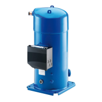
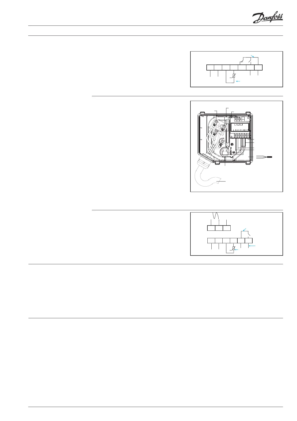
The motor protection module comes pre-
installed within the terminal box and has
pre-wired thermistor connections. The module
must be connected to a power supply of the
appropriate voltage. The module terminals are
6.3 mm size.
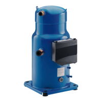
The terminal box is
provided with 2 triple
knockouts and 1 single knockout for power
supply and 4 double knockouts for the safety
control circuit.
The 3 power supply knockouts accommodate the
following diameters:
• Ø 50.8 mm (UL 1"1/2 conduit) &
Ø 43.7 mm (UL
1"1/4 conduit) & Ø 34.5 mm (UL 1" conduit)
• Ø 40.5 mm (ISO40) & Ø 32.2 mm (ISO32) & Ø
25.5 mm (ISO25)
• Ø 25.5 mm (ISO25)
The 4 others knockouts are as follows:
• Ø 22.5 mm (PG16) (UL 1/2") & Ø 16.5 mm
(ISO16) (x2)
• 20.7 mm (ISO20 or PG13.5) (x2)
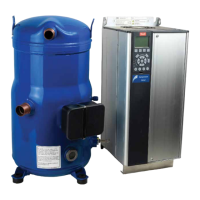
SH240-295-300-380-485
The motor protection module comes preinstalled
within the terminal box. Phase sequence
protection connections and thermistor
connections are pre-wired. The module must be
connected to a power supply of the appropriate
vo
ltage. The module terminals are 6.3-mm size
Faston t ype.
The temperature inside the terminal box may not
exceed 70°C. Consequently, if the compressor is
installed in an enclosure, precautions must be
taken to avoid that the
temperature around the
compressor and in the terminal box would rise
too much. The installation of ventilation on the
enclosure panels may be necessary. If not, the
electronic protection module may not operate
properly. Any compressor damage rel
ated to this
will not be covered by Danfoss warranty. In the
same manner, cables must be selected in a way
to insure that terminal box temperature does not
exceed 70°C.
Terminal box
temperature
IP rating
The compressor terminal box according to IEC529 is IP54 for all models when correctly sized IP54 rated
cable glands are used.
First numeral, level of protection against contact and foreign objects
5 - Dust protected
Second numeral, level of protection against water
4 - Protection
against water splashing
LN1 2 1412 11
Internal control contact
Safety
circuit
Thermistor
connection
Module power
L N S1 S2 M1 M2
L1 L2 L3
Black Blue Brown
Phase sequence input
Internal contr ol contact
Safety
circuit
Thermistor
connection
Module power
Black
Blue
Brown
M1 - M2
Control circuit
Faston 1/4” tabs
Power supply
Sump heater
Module
power supply
}
}
 Loading...