27
FRCC.PC.007.B8.02
Application guidelines
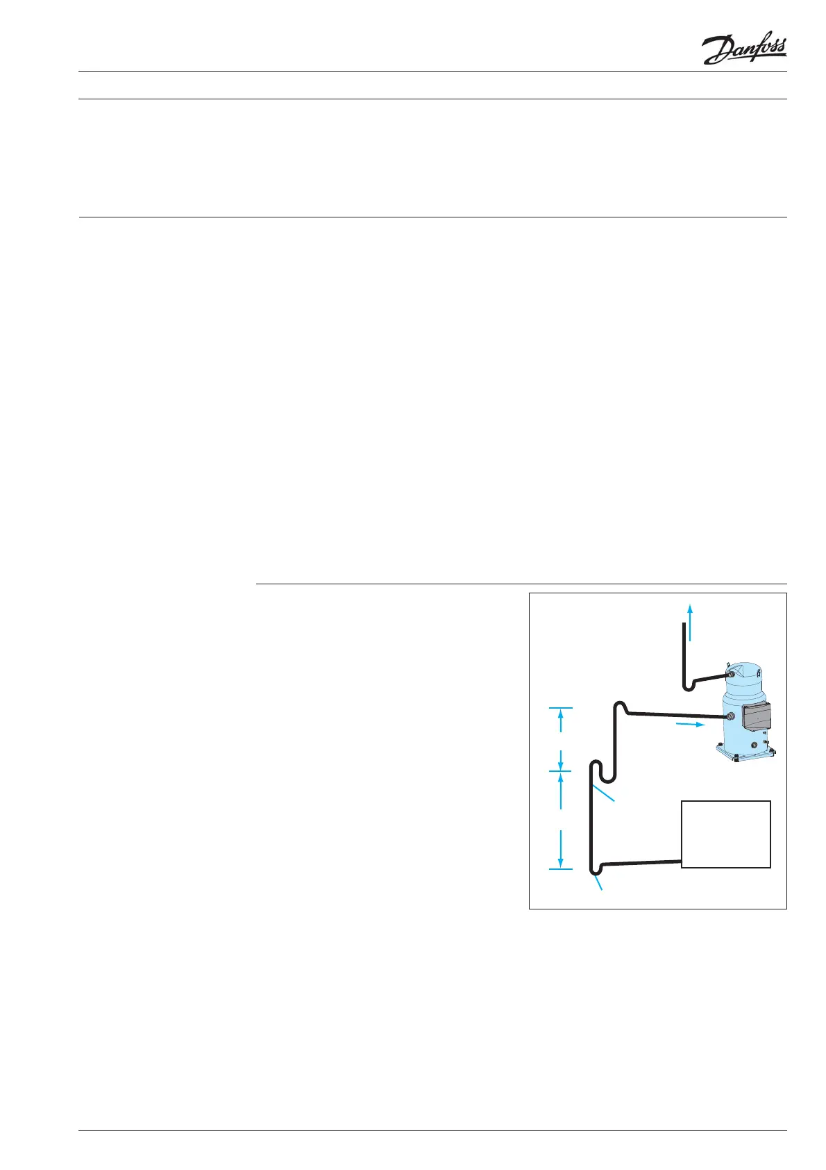
If the evaporator lies above the compressor, as
is often the case in split or remote condenser
systems, the addition of a pump-down cycle
is strongly recommended. If a pump-down
cycle were to be omitted, the suction line must
have a loop at the evaporator outlet to prevent
refrigerant from draining into the compressor
during o -cycles.
If the evaporator were situated below the
compressor, the suction riser must be trapped so
as to prevent liquid refrigerant from collecting at
the outlet of the evaporator while the system is
idle, which would mislead the expansion valve’s
sensor (thermal bulb) at start-up.
System design recommendations
The working pressure in systems with R410A is
about 60% higher than in systems with R22 or
R407C. Consequently, all system components and
piping must be designed for this higher pressure
level.
Proper piping practices should be employed to
ensure adequate oil return, even under minimum
load conditions with special consideration given
to the size and slope of the tubing coming
from the evaporator. Tubing returns from the
evaporator should be designed so as not to trap
oil and to prevent oil and refrigerant migration
back to the compressor during o -cycles.
In systems with R410A, the refrigerant mass
ow will be lower compared to R22/R407C
systems. To maintain acceptable pressure
drops and acceptable minimum gas velocities,
the refrigerant piping must be reduced in size
compared to R22 / R407C systems. Take care not
to create too high pressure drops since in R410A
systems the negative impact of high pressure
drops on the system e ciency is stronger than in
R22/R407C systems.
Piping should be designed with adequate three-
dimensional exibility. It should not be in contact
with the surrounding structure, unless a proper
tubing mount has been installed. This protection
proves necessary to avoid excess vibration, which
can ultimately result in connection or tube failure
due to fatigue or wear from abrasion. Aside from
tubing and connection damage, excess vibration
may be transmitted to the surrounding structure
and generate an unacceptable noise level within
that structure as well. For more information on
noise and vibration, see the section on: «Sound
and vibration management».
Successful application of scroll compressors
is dependent on careful selection of the
compressor for the application. If the compressor
is not correct for the system, it will operate
beyond the limits given in this manual. Poor
performance, reduced reliability, or both may
result.
Essential piping design
considerations
General
Suction lines
HP
4 m/s or more
0.5% slope
To condenser
max. 4 m
max. 4 m
0.5% slope
U-trap, as short as possible
U-trap
4m/s or more
U trap, as short as possible
Evaporator
LP
8 to 12 m/s
 Loading...