18
FRCC.PC.007.B8.02
Application guidelines
Suggested wiring diagrams logic
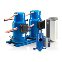
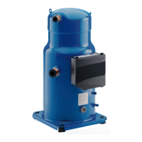
Compressor model SH 090 - 105 - 120 - 140 - 161 - 184
Electrical data, connections and wiring
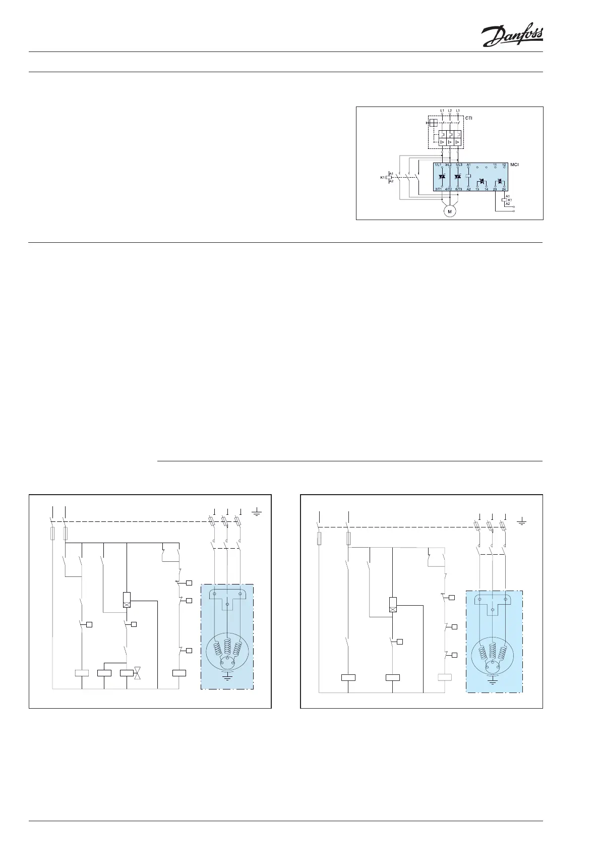
By means of the built-in auxiliary contact (23-24)
the by-pass function is easily achieved, see wiring
diagram beside.
No heat is generated from the MCI. As the
contactor always switches in no-load condition
it can be selected on
the basis of the thermal
current (AC-1).
13-14 contact not applicable with MCI 25C.
MCI with by-pass contactor
General wiring
information
The wiring diagrams below are examples for a
safe and reliable compressor wiring. In case an
alternative wiring logic is chosen, it is imperative
to respect the following rules:
When a safety switch trips, the compressor must
stop
immediately and must not re-start until
the tripping condition is back to normal and
the safety switch is closed again. This applies to
the LP safety switch, the HP safety switch, the
discharge gas thermostat and the motor safety
thermostat.
In speci c sit
uations, such as winter start
operation, an eventual LP control for pump-
down cycles may be temporarily bypassed to
allow the system to build pressure. But it remains
mandatory for compressor protection to apply an
LP safety switch. The
LP safety switch must never
be bypassed.
Pressure settings for the LP and HP safety switch
and pump-down listed in table from section "Low
pressure".
When ever possible (ie. PLC control), it is
recommended to limit the possibilities of
compressor auto restart to less than 3 to 5 times
during a period of 12 hours when caused by
motor protection or LP safety switch tripping.
This control must be managed as a manual reset
device.
M
DGT
HP
LPS
180 s
TH
LP
CONTROL CIRCUIT
F1F1
KM
KM
KM
KA KA
A1
A2
A3
KA
KA
KS
KS
KS
L1 L3 L2
Q1
T1
T3
T2
LLSV KS
Wiring diagram with pump-down cycle
KM
L1 L3 L2
Q1
CONTROL CIRCUIT
F1F1
KM KA
KA KS
KS
KS
HP
DGT
TH
180 s
85 52 019 - A
T1
T2
M
T3
KA KA
A1
A2
A3
Wiring diagram without pump-down cycle
LPS
 Loading...