19
FRCC.PC.007.B8.02
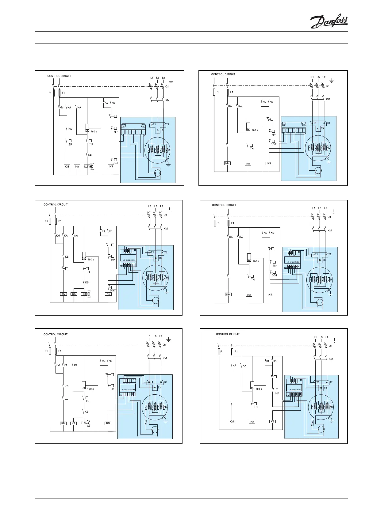
Application guidelines
Electrical data, connections and wiring
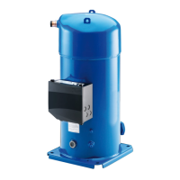
Compressor models SH 180
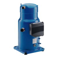
Compressor model SH240-295-300-380
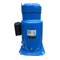
Compressor model SH485
Fuses ..................................................................................................F1
Compressor contactor ................................................................ KM
Control relay ...................................................................................KA
Safety lock out relay ......................................................................KS
Optional short cycle timer (3 min) .......................................180 s
External overload protection ......................................................F2
Pump-down pressure switch ......................................................LP
High pressure safety switch ........................................................HP
Control device ................................................................................TH
Liquid Line Solenoid valve ...................................................... LLSV
Discharge gas thermostat / thermistor ................................DGT
Fused disconnect ...........................................................................Q1
Motor safety thermostat ...........................................................thM
Compressor motor ..........................................................................M
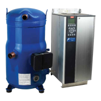
Motor Protection Module ...................................................... MPM
Thermistor chain .............................................................................. S
Safety pressure switch ................................................................LPS
Legend
A1
A3
A2
LPS
MPM
12
14
11
N
2
1
L1
Wiring diagram without pump-down cycle
A1
A3
A2
LPS
Motor Protection
12
14
11
N
2
1
Module
L1
Wiring diagram with pump-down cycle
A1
A3
A2
MPM
S
LPS
Wiring diagram with pump-down cycle
LP
A1
A3
A2
MPM
S
LPS
DGT
Wiring diagram with pump-down cycle
LP
A1
A3
A2
MPM
S
KS
Wiring diagram without pump-down cycle
LPS
A1
A3
A2
MPM
S
KS
Wiring diagram without pump-down cycle
LPS
DGT
 Loading...