6
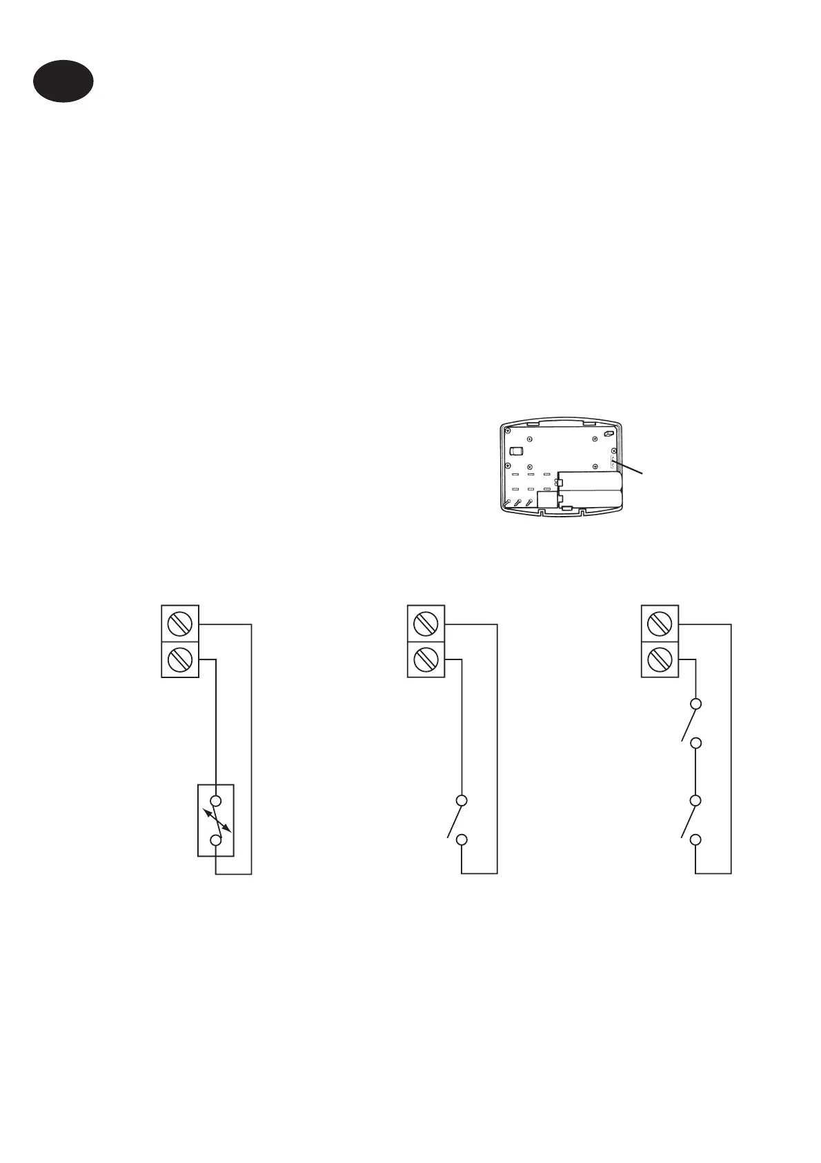
Models with remote sensor inputs
Terminal block for remote control/
sensing is located on the circuit board
above the battery compartment.
Installation Instructions
GB
S1/D
S2/E
S1/D
S2/E
Window or
teleswitch
contact
(NO or NC)
S1/D
S2/E
Teleswitch
contact (NC)
Window
contact (NC)
Con gured for
remote room
sensor or limit
sensor
Con gured for
window contact or
other contact such
as teleswitch
Con gured for
window contact
and other contact
such as teleswitch
D
E
Remote
control
connections
Battery powered
verions
!
Some existing thermostats will have a Neutral and/or Earth wire connected. These
are not required by the battery powered versions of the TP5000 Si and must NOT be
connected to any battery powered TP5000 Si terminals. Instead they should be made
electrically safe and coiled in the recess at the back of the TP5000 Si.
Models with remote sensor inputs
The TP5000A Si, TP5000A-RF Si and TP5000MA Si incorporate an input
which can be used to connect one of the following:
1) remote room temperature sensor (sold as accessory).
2) limit sensor, for example, oor temperature sensor (sold as
accessory).
3) window contacts, card reader contacts or teleswitch contacts.
See Installer Advanced Programming Options for set-up instructions.
Note:
Battery powered versions use S1 and S2.
Mains powered versions use D and E.