Page 100 of 108
M-AP-001-EN Rev. N
M-AP-001-EN Rev. N
Installation
20.7 Power Wiring This section describes the connection of the power wiring to the compressor.
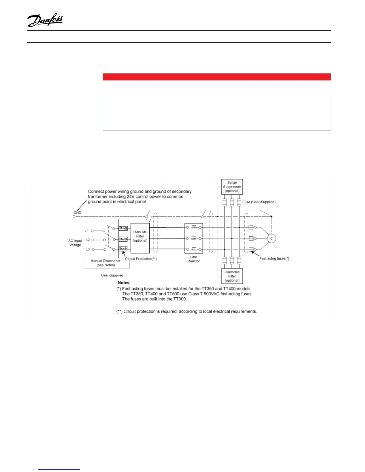
Figure 20-9 shows a typical schematic for the compressor’s electrical connections.
Figure 20-9 - Typical
Electrical Connections
NOTE
The AC input cable should be CSA, UL, or CE approved, 3-wire with a common shield and single ground. It is recommended that
the cable be double-jacketed; for example, a teck cable type. The cable must be rated for 90° C (194° F) minimum with a maximum
current rating corresponding to the LRA value on the compressor nameplate.
Keep power cables and control interface cables in separate conduits. Use metal cable glands for shielded cables to ensure good
grounding.
If you are installing a DTC line reactor or EMI or harmonic lter in the mains input circuit, refer to the applicable installation
instructions.
1. Release the screws that secure the mains input cover to the compressor. Lift away
cover.
2. Insert a cable gland (customer-supplied) into the opening in the mains input bracket.
3. Fasten the cable gland to the bracket with the locknut
4. Feed the AC input cable through the cable gland.
 Loading...


