27 of 132
M-SV-001-EN Rev.E
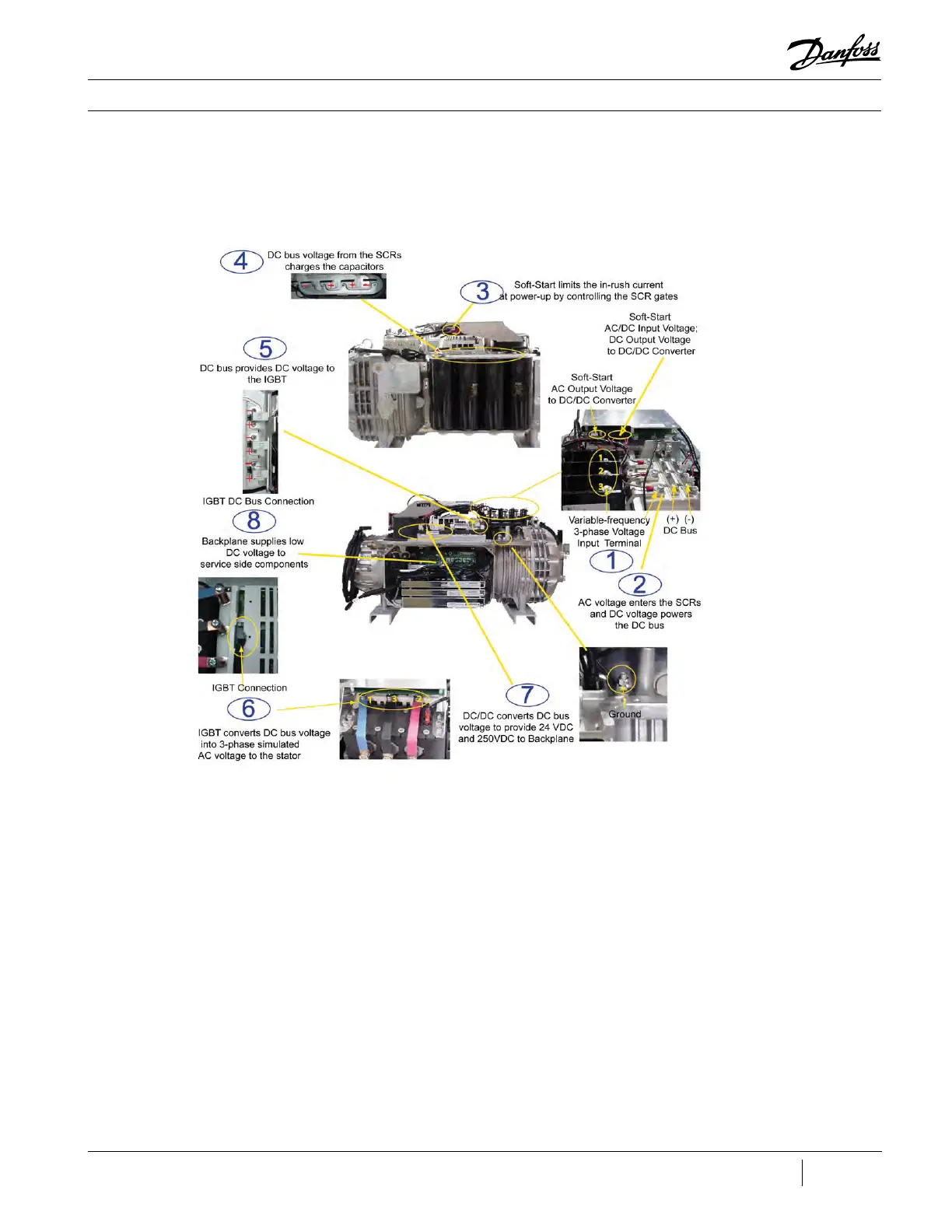
The order of power and signal flow through
the compressor components is as follows (see
Figure 17 (Compressor Energy and Signal Flow
Connections (TT300/TG230 Shown)):
1. A 3-phase voltage source is provided to the
compressor through the voltage input terminal.
2. AC voltage enters the SCRs and DC voltage
powers the DC bus.
3. The Soft Start Board limits the in-rush current
at power-up by controlling the SCR gates.
4. DC bus voltage from the SCRs charges the
capacitors.
5. DC bus provides DC voltage to Inverter.
6. The Inverter converts the DC bus voltage into a
variable frequency, 3-phase simulated AC voltage
to the Stator.
7. The HV DC-DC Converter uses the DC bus
voltage to provide 24VDC and 250VDC to the
Backplane.
8. The Backplane connects and supplies low DC
voltage to the service side components.
Refer to Figure 18 (Compressor Energy and
Control Flow Block Diagram) for a block diagram
summary of the energy and voltage signal flow
through the compressor.
Compressor Fundamentals
Figure 17 - Compressor
Energy and Signal Flow
Connections (TT300/TG230
Shown)
 Loading...


